
An Optical Splitter, also known as a beam splitter, is a passive optical device that divides a single input optical signal into two or more output signals. Conversely, it can also combine multiple signals into one. Knowing the difference between a splitter and an optical coupler helps you build better networks. You make your network work better when you pick the right device for each job. You can connect many users to one port with 1:n or 2:n splitters. By dividing a single optical signal from a central Optical Line Terminal (OLT) into multiple outputs for Optical Network Terminals (ONTs) at users' homes, splitters eliminate the need for dedicated fibers to each residence—slashing infrastructure costs while scaling network reach. This guide. In a Passive Optical Network (PON), a single optical fiber carries massive amounts of data using light. Signal Input: The fiber splitter receives the optical signal from the upstream network node and enters the splitter through the input fiber. Signal Distribution: Inside the splitter, according to the design structure and different. Splitters are passive optical devices that divide or combine optical signals, and they come in various types, including power splitters, uneven splitters, and wavelength-division multiplexing (WDM) splitters. Each type serves specific applications, enabling efficient use of optical infrastructure.
[PDF]

Cable Trays* — Max two 24 in. (610 mm) wide by max 6 in. (151 mm) deep open-ladder cable tray with channel-shaped side rails formed of 0. 54 mm) thick aluminum or min 0. In practice, cable tray dimensions are a system of interrelated measurements —width, depth, length, and material thickness—that directly affect cable fill compliance, heat dissipation, structural loading, and long-term expandability. From an engineering standpoint, cable tray dimensions are not. Perforated Cable Tray System expertly constructed from high-grade stainless steel, offering exceptional durability and resistance to corrosion. With side height 100mm. A properly designed and installed cable tray system will provide. Studs — Wall framing to consist of wood studs or channel shaped steel studs. Wood studs to consist of nom 2 by 4 in. Additional studs shall be used to completely frame. Best Size: Here, deep trays (75mm to 150mm) are used since power cables are typically thick and heavy. Data cables, such as your Wi-Fi or computer ones, are extremely sensitive. They do not get hot; however, they do not like to hang or sag. In case a data cable folds in an excessive manner, the. ect the minimum bend ra-dius for cables as they exit the bottom of the cable tray. A rung spacing of 6 to 9 inches (150 to 230 mm) is preferable when the cable tray cont d for instrumentation and control applications that require additional protec eferred to support and protect numerous small.
[PDF]

Per‑unit estimates often appear as $0. 50 per ft for basic fiber plus additional charges for trenching and install labor. Several drivers shape fiber installation pricing. Homeowners and businesses typically pay for fiber optic cable installation based on distance, conduit needs, and labor. The main cost drivers include material type, run length, trenching or aerial work, and any required permits or inspections. This guide provides clear cost estimates, price ranges. The initial cost of installing fiber optic cables can vary depending on the chosen installation method and specific project requirements. Total Project Costs: For commercial installations, expect costs ranging from $5,000 to $20,000 per mile for underground projects and from $40,000 to $60,000 per. Buyers typically pay for fiber laying by combining material costs, labor time, and permitting plus trenching or aerial support fees. A short residential drop under 1,000 ft may cost $3,000-$8,000, while longer runs to an attached garage or street node can run $8,000-$25,000. The price often reflects project scope, geography, and local regulations, making. Fiber optic cable costs vary widely – from $0. Installation can be more expensive than the cable itself, especially with site challenges.
[PDF]

The optical module is usually composed of Transmitter Optical Subassembly (TOSA, containing a laser LD Chip), Receiver Optical Subassembly (ROSA, containing a photodetector PD Chip), a driving circuit, and an optical and electrical interface. Its schematic is shown in. This section explains the structure of a typical pigtail butterfly module, which gets its name from the two rows of seven leads at right angles on each side of the metal package plus an optical fiber pigtail at one end (Fig. Let's look at the internal structure (Fig. 2) of a common butterfly. Optical modules are devices used to connect network devices, transmit and receive data between network devices, and can be used to convert optical and electrical signals. The optical module is a very important component in an optical communication system. Optical devices are the core components of optical modules. TOSA and ROSA in Common Optical Transceiver Modules For ordinary optical transceiver modules, there are two optical devices, TOSA and ROSA, which have opposite effects.
[PDF]

Run the display transceiver [ interface interface-type interface-number | slot slot-id ] [ verbose ] command to view information about the optical module on a specified interface. In optical communication equipment, an optical module (Optical Module) contains several types of semiconductor chips that work together to complete the transmission and processing of optical signals. These chips typically include laser chips, photodetector chips, driver chips, transimpedance. When the optical module on an interface is faulty, you can run the display commands to view information about the optical module. Today, we will deeply analyze the four mainstream models of 100G QSFP28 dual-fiber optical modules: QSFP28-100G-SR4, QSFP28-100G-LR4, QSFP28-100G-ER4 and. The following uses the Moduletek SFP-10G-LR module connected to a Huawei S6700 switch as an example to introduce how to read information of the connected optical module on a Huawei switch. Figure 1 Schematic Diagram of Optical Module Connected to Switch 1. Optical Module Status Check Run the. Upgrade to 100G or 400G optics and save. Cisco Transceiver Modules - Learn product details such as features and benefits, as well as hardware and software specifications. Network administrators have a major challenge determining the right Cisco SFP modules, understanding complex model numbers that directly affect network performance and stability.
[PDF]

Explore 74 top manufacturers and suppliers of Optical Testing Instruments in our comprehensive photonics buyers' guide. An optical testing instrument is a device or system used to evaluate and measure the performance, quality, and characteristics of optical components. Source Photonics, founded in 1988 and based in Los Angeles, California, is a technology company that specializes in optical transceivers and data connectivity solutions. The company provides a wide range of products tailored for data centers, broadband, and optical transmission, serving. CACI designs and manufactures optical communications terminals for all of the major orbits in which our customer missions operate. These bespoke solutions are being manufactured in Orlando at CACI's space manufacturing and testing facility, which opened in June 2022. The facility is dedicated to. Manufacturer of standard and custom opticaltestequipment including microscopes, pocket comparators, disc gages, grids, scales, strips, slits, and micrometers. Suitable for optical, gaging, imaging, and calibration applications. Serves aviation industry. Lapmaster Wolters is estimated to have. Optical transceivers are devices that convert electrical signals into optical signals for transmission and reception. They are primarily used in communication systems that employ optical fiber cables, serving the purpose of signal conversion between the transmitting and receiving ends.
[PDF]

An optical transceiver module, often simply called an optical module, acts as a signal conversion interface in fiber optic networks. It transforms high volumes of electrical signals into optical signals for transmission over fiber cables, or reverses the process at the receiving. In the world of fiber optic communications, optical transceiver modules play a pivotal role as interfaces that convert electrical signals to optical signals and vice versa. If you're dealing with data centers, telecommunications, or AI networking, grasping the key parameters of an optical. Optical transceivers are efficient in changing signals. These modules have many parts, each with a specific functions: Takes in electrical signals to change them. Powers lasers or LEDs to send light signals. Combines many light signals into one for. An optical transceiver, a crucial device utilized in optical communication, is an optoelectronic element, allowing the interconversion of optical and electrical signals during the information transmission. Acting as the "heart" of fiber-optic networks, these modules—ranging. This comprehensive guide breaks down the internal structure, core components (TOSA, ROSA, lasers), and operational mechanisms of SFP optical modules, enriched with technical insights and real-world applications.
[PDF]

Optical Modules Market Segments - by Product Type (Transceivers, Receivers, Transmitters, Amplifiers, and Others), Application (Data Centers, Telecommunication, Enterprise Networking, and Others), Distribution Channel (Online Stores, Direct Sales, Indirect Sales . Optical Modules Market Segments - by Product Type (Transceivers, Receivers, Transmitters, Amplifiers, and Others), Application (Data Centers, Telecommunication, Enterprise Networking, and Others), Distribution Channel (Online Stores, Direct Sales, Indirect Sales . Data centers will keep dominating optical module demand as AI and cloud drive revenue growth through 2030. Optical module demand is being pulled in two directions at once, faster bandwidth for dense networks and tighter constraints on power, security, and lead times. 8% during the forecast period 2025-2031. The potential shifts in the 2025 U. tariff framework pose substantial volatility. The Optical Module Market size was estimated at USD 26. 53 billion in 2025 and expected to reach USD 30. The accelerating explosion of global data traffic has thrust optical modules into the heart of modern communications.
[PDF]

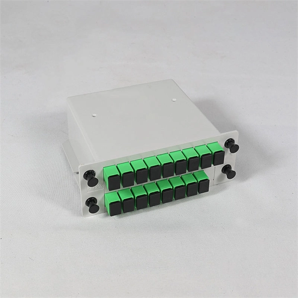
Here's a step-by-step guide to help you set up your fiber distribution box seamlessly: Before installing the fiber distribution box, ensure that your optical cables are properly prepared for connection. The optical fiber distribution box allows people to easily access the optical fibers in the box, and can well protect the optical fibers. In addition, the drawer structure also facilitates high-density wiring and good cable management. However, because optical fibers are fragile and can be easily. Keeping this page as a placeholder for now. Have any questions? Talk with us directly using LiveChat. Fix the rack to the ground with expansion bolts. Top installation: Dimensions of four connection holes on the top according to the. This instruction describes the installation of the Fiber Distribution Frame (FDF) manufactured by Corning Optical Communications. To order accessories that are purchased separately, contact Corning Optical Communications customer care for assistance. Read and understand this procedure (as well as. Optical fiber distribution frame is the wiring connection equipment between optical cable and optical communication equipment or between optical communication equipment. Distribution boxes are especially essential for FTTH networks, where they enable the efficient connection and management of optical fibers from a central.
[PDF]

Here at AFL we provide years of experience and excellent solutions for your hardware needs in both ADSS (All-Dielectric Self Supporting), OPGW (Optical Ground Wire) and SkyWrap cables. Please follow the links below for assistance in choosing your hardware. The aluminum Opti-LoopTM FOS for All Dielectric Self Support (ADSS) cable is available in 3 sizes. With more than one million units in service, Opti-Loop fiber storage systems lead the industry in quality and durability. All aluminum construction with continuous welds at crossbars and ends. Each. Also see our line of ADSS Fiber Optic Cable. © Copyright 2026 AFL. Our product experts are here to assist you. Get in touch with our team now. PLP transmission, distribution, substation, fiber optic, solar, and EV solutions protect and connect overhead electric power lines and communications networks. ADSS Anchor Tension Clamps are hardware fittings used to securely terminate and anchor ADSS fiber optic cables on poles or towers without damaging the cable. This is a type of self-supporting optical fiber cable that does not require any kind of support in distributing electricity from one point to another. As much as they may be independent, these cables are usually installed on poles and.
[PDF]

A ceramic sleeve is a small, cylindrical element employing zirconia, which is a strong, low thermal expanding ceramic used in a fiber optic system to locally align and hold the interface between the fibers or connectors. It ensures precise alignment. Known for their high-temperature resistance, wear resistance, and chemical stability, ceramic sleeves have become a key element in applications spanning communications, electronics, automotive, aerospace, and industrial systems. The industry is developing in a diversified manner, connecting raw. Most of the ferrules used in optical connectors are made of ceramic (Zirconia) material due to some of the desirable properties they possess. Kyocera's extrusion molding process creates ferrules with excellent coaxiality, and our precision machining ensures excellent concentricity with precise. Alignment sleeves are the primary mechanical reference inside a fiber optic adapter. Their role is to constrain lateral offset, angular deviation, and axial separation between mating ferrules, directly determining insertion loss and return loss stability. Historically, both ceramic and phosphor. The global market for ceramic sleeves is experiencing robust growth, projected to reach an estimated $287 million by 2025. This expansion is fueled by an impressive CAGR of 20. 5% during the study period. The primary drivers for this surge are the increasing demand for high-performance optical.
[PDF]

NPO (Near-Packaged Optics) is a transitional technology bridging traditional pluggable modules and CPO. It integrates the optical engine and GPU chip side-by-side on the same high-performance PCB or organic substrate, connected via ultra-short high-speed circuits. Its core concept is to remove digital processing units such as DSPs and CDRs from the module, constructing a purely analog "linear direct-drive" optical link. In the LPO architecture: The transmitter uses a high-linearity driver chip to directly drive the optical modulator, converting the. Near-packaged optics (NPO) helps send data faster. It puts the optical engine close to the switching chip. This makes things work better. NPO lets you upgrade easily. You do not have to redesign your whole system. It lowers energy costs. Among the emerging technologies, LPO (Linear Pluggable Optics), NPO (Near-Packaged Optics), and CPO (Co-Packaged Optics) represent three important stages in the evolution of next-generation data center optical networking. Understanding how these architectures differ is essential for designing. Traditional optical modules typically rely on DSPs (Digital Signal Processors) to handle signal equalization, retiming, and compensation, mitigating attenuation and distortion during transmission. They are not concepts at the same level, but rather.
[PDF]

Select the correct wavelength and set your reference. You measure optical power in dBm or insertion loss in dB. Consistent procedures ensure accuracy. Measure total signal loss from fiber, connectors, or splices. Optical fiber attenuation is the attenuation per unit length of optical fiber, and the unit is dB/km. When connecting two optical fibers, there will be loss inside any connector or joint. Consistent measurement techniques. While optical power meters are the primary power measurement instrument, optical loss test sets (OLTSs) and optical time domain reflectometers (OTDRs) also measure power in testing loss. TIA standard test FOTP-95 covers the measurement of optical power. Optical power is based on the heating power. Light Source: The CMA5 Series Light Sources provide an economical and stable laser source for use in point-to-point attenuation measurement. They feature a rugged design, built to withstand the difficult testing environment of fiber optic cable installation and maintenance. The CMA5 Light Sources. When talking about optical measurements, wavelength basically means how far a wave pattern repeats itself, usually measured in nanometers (nm). Commonly, a power meter on its own is used to measure absolute.
[PDF]
Cambodia Fibre Optic Communication Networks Co., Ltd (CFOCN) has requested the Ministry of Public Works and Transport (MPWT) for approval to undertake a project involving the drilling and installation of new fibre optic cables across Cambodia's nine major provinces. This request was discussed during a meeting. Established since 2022, and obtained a license from Telecommunication Regulator of Cambodia (TRC) Who We Are? Established in 2022, and obtained a license from the Telecommunication Regulator of Cambodia (TRC). – Cambodia Licensed Provider for Operation and Provision of Telecommunications Cable. Telcotech is Cambodia's trusted choice of Telecommunication Infrastructure and Associated Services Provider. With a 30,000-kilometer-long. The project company comprises investment of two fiber optic telecommunication networks which are the undersea fiber optic cable Asia-Africa-Europe 1 (AAE-1) and the land cable network (the 'Project'), as detailed in the following report. The project will be developed by (Cambodia) Fiber Optic. Phnom Penh (FN), Aug. 14 – Telcotech is one of the market leaders for infrastructure in Cambodia, subsea cable and also connectivity in the region, announced the cooperation with Huawei building Cambodia's first nationwide next generation transport network. It is understood that the network will.
[PDF]
Glass fiber and plastic fiber is fragile. When individual fibers break, light transmission and uniformity are reduced. After the first few fibers break at a stress point, a chain reaction occurs, hastening t.
[PDF]
