Cable Trays* — Max two 24 in. (610 mm) wide by max 6 in. (151 mm) deep open-ladder cable tray with channel-shaped side rails formed of 0. 54 mm) thick aluminum or min 0. In practice, cable tray dimensions are a system of interrelated measurements —width, depth, length, and material thickness—that directly affect cable fill compliance, heat dissipation, structural loading, and long-term expandability. From an engineering standpoint, cable tray dimensions are not. Perforated Cable Tray System expertly constructed from high-grade stainless steel, offering exceptional durability and resistance to corrosion. With side height 100mm. A properly designed and installed cable tray system will provide. Studs — Wall framing to consist of wood studs or channel shaped steel studs. Wood studs to consist of nom 2 by 4 in. Additional studs shall be used to completely frame. Best Size: Here, deep trays (75mm to 150mm) are used since power cables are typically thick and heavy. Data cables, such as your Wi-Fi or computer ones, are extremely sensitive. They do not get hot; however, they do not like to hang or sag. In case a data cable folds in an excessive manner, the. ect the minimum bend ra-dius for cables as they exit the bottom of the cable tray. A rung spacing of 6 to 9 inches (150 to 230 mm) is preferable when the cable tray cont d for instrumentation and control applications that require additional protec eferred to support and protect numerous small.
[PDF]

In this article, we'll provide step-by-step instructions on how to install a round junction box in a wall, as well as tips on safety and proper wiring techniques. First, you need to determine the. A junction box provides a code-approved place to house wire connections, whether for outlets, switches, or splices. Here's how to install one. We may be compensated if you purchase through links on our website. It acts as a central connection point for various electrical wires, allowing for the easy distribution of electricity to different fixtures and devices. A properly installed and wired junction box ensures the safety and. Nothing is more dangerous and aggravating than loose wires in a junction box. In this video you'll learn how to wire junction boxes correctly. You'll also see our favorite tools to complete this task. Thanks for watching and Have A Great Day. more. Learn how to install a junction box safely, from choosing the right box and mounting it correctly to making secure splices and following basic code-safe practices. This metal or plastic housing contains wire connections, protecting them from environmental factors and physical damage. Junction boxes are fundamental in residential and.
[PDF]

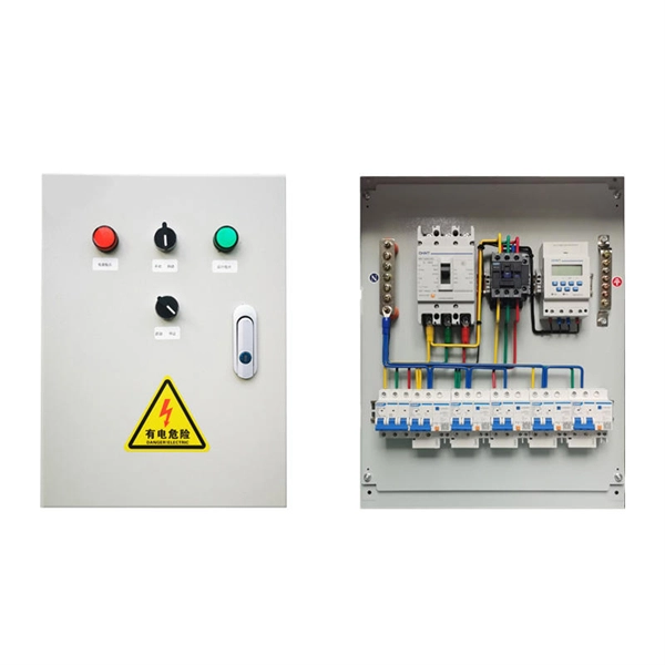
This video shows real on-site footage of electrical installation, demonstrating safe and standardized wiring methods used by professionals. more Learn how to wire a distribution box step by step! This video shows real on-site footage of. Understanding the wiring diagram of an electrical panel box is essential for electricians and homeowners alike, as it allows them to troubleshoot any electrical issues, carry out repairs, or make additions to the system. The electrical panel box wiring diagram provides a visual representation of. A distribution box, also known as an electrical distribution board, is a critical component in electrical systems. It serves as a central point for distributing electricity to various circuits in a building or facility. This section will explain its function, types, and the importance of correct. Understanding how to safely set up the main connections of a home's power distribution system is essential for ensuring reliable and secure operation. A correct installation process minimizes the risk of electrical faults and increases the longevity of your setup. Proper knowledge is crucial for. Material preparation: Prepare the required circuit breakers, wires, wiring ties and other materials, and ensure that they meet the design drawings and installation requirements. Whether you're an electrician or a DIY enthusiast, this guide will help you understand the basics of home electrical distribution. What is Distribution Board? Distribution board.
[PDF]

In this video, we'll show you how to connect an energy meter to a distribution board (DB) safely and efficiently. energy meter connection with distribution box How to Connect an Energy Meter to Your Distribution Box Easily Steps to Properly Connect Your Energy Meter to a Distribution Box. It plays a vital role in ensuring the safe and efficient distribution of electricity throughout the premises. What is the wire from the meter to the breaker box? Also. Always begin with disconnecting the main supply before accessing any enclosure containing distribution components. This prevents arc faults and ensures safety when modifying or inspecting current paths. This “meter to panel” wiring establishes the pathway for all incoming electrical power from the grid to the home. Its primary function is to safely and reliably. Distribution Board aslo know as “Panel Board”, “Switch & Fuse Board” or “Consumer Unit” is a box installed in the building containing on protective devices, such as circuit breaker, fuses, isolator, switches, RCDs and MCBs etc. The electric main supply (230V AC & 120V AC in US) is connected through. Changed Texas's reference diagram for the 3 wire network 120/208 Volt single phase self-contained Revised Figures 13, 14, 14b. Limited the meter location from pad mount transformer for PSO. Removed unistrut being listed as an alternative means for mounting the meter box. APCo and TX do not allow.
[PDF]

A neat, well-organized subpanel bundles wires to conserve space and improve access. Ideally, wire groups are installed in layers and wires are bent at right angles to buses or breakers. Label short sheathing sections (slugs) to indicate which circuits wires serve. We cover everything from separating color-coded wires and securing them with ties to. Discover 7 DIY tips to organize your electrical panel for improved safety, easier troubleshooting, and efficient maintenance. Prevent hazards while making your home's electrical system more manageable. A disorganized electrical panel isn't just an eyesore—it's a safety hazard and troubleshooting. According to NEC (National Electric Code: Article 1 00-Definitions), a Main Panel (also known as Panelboard, load center, breaker box and distribution board etc. ) is a cabinet or cutout box which contains on controlling and protective devices (such as circuit breakers, fuses, switches etc. ) used to. Welcome to this live training session! ⚡ In today's tutorial, I'll be demonstrating how to arrange cables neatly inside a distribution bo. more See what others said about this video while it was live. If you're struggling with unsightly cords hanging around your cabinets, worry not! In this guide, we'll explore practical strategies to conceal those wires effectively. Before starting the process of.
[PDF]

Learn how to safely wire a single-pole (one way) light switch in this beginner-friendly tutorial. Whether you're replacing an old switch or doing your first DIY electrical project, this guide will walk you through every step — no experience needed!. more. This page contains wiring diagrams for household light switches and includes: a switch loop, single-pole switches, light dimmer, and a few choices for wiring an outlet/switch combo device. That's because virtually all light switches that control 120-volt fixtures are single-pole switches. Most light switches are also single-throw, which. Summary: Fully explained wiring diagrams and photos show how to wire switches including: single switches, 3-way switches, 4-way switches, and dimmer switches. and Be Sure to Subscribe! Make sure the circuit power has been turned off, and mark the circuit breaker or fuse to indicate that work is. A distribution board or distribution box is where the main power supply is distributed to multiple loads. And all the switching and protective devices are installed in the distribution box. Single Phase Distribution Box generally consists of Double Pole MCBs, Single Pole MCBs, and RCCBs. Wiring a single light switch may seem like a daunting task, but with the right tools, a bit of patience, and this comprehensive guide, you'll be able to tackle this DIY project with confidence. Remember, while this guide provides detailed instructions, always prioritize safety and consult a.
[PDF]

In this complete wiring diagram guide, we will walk you through the step-by-step process of wiring a mag starter. We will explain the purpose and function of each component, provide clear diagrams, and offer expert tips to ensure a successful installation. Whether you're a beginner or an. For proper integration of an electromagnetic securing device, ensure the power supply matches the specified voltage–typically 12V or 24V DC. Incorrect voltage can cause malfunction or reduced holding force. Use a regulated power source to prevent current fluctuations that might trigger false alarms. Understanding the wiring diagram of a magnetic starter is essential for technicians and electricians who work with electric motors. This diagram provides a visual representation of the components and connections involved in the operation of the starter. Once you have everything ready, you can proceed with the installation process. Begin by determining the appropriate position for the magnetic lock on the door. Quick guide on how to wire an access control system with power supply, lock, and exit button. more Quick guide on how to wire an access control. Installing a magnetic door lock can be a cost-effective and reliable way to secure your doors. These locks use an electromagnetic current to keep the door securely closed, and they are commonly used in commercial and residential buildings.
[PDF]

This video shows real on-site footage of electrical installation, demonstrating safe and standardized wiring methods used by professionals. In this guide, we'll break down everything you need to know to install a distribution box correctly and confidently. Choose the right box based on environment (indoor/outdoor), load capacity, and durability. Check for proper IP/NEMA ratings and material quality. more Learn how to wire a distribution box step by step! This video shows real on-site footage of. This guide provides step-by-step instructions for connecting a distribution box and highlights key factors to consider during installation. What Is a Distribution Box? A distribution box, also known as an electrical distribution board, is a critical component in electrical systems. It serves as a. Material preparation: Prepare the required circuit breakers, wires, wiring ties and other materials, and ensure that they meet the design drawings and installation requirements. Location determination: Determine the installation position of the circuit breaker according to the position of the. A cable distribution box is an electrical device used to collect, distribute, and protect electrical power. It serves as a central hub for distributing electricity throughout a building, ensuring that power is delivered safely and efficiently to all the required locations.
[PDF]
Reach inside panels, disconnects, and raceway to bend and position heavy duty cable with greater precision and less fatigue than bending by hand. The dies on the ends of these benders are sized to handle large wire gauges; fit your cable into the dies and push or pull the handle to bend. Smooth. Check each product page for other buying options. Need help? Online shopping for Tools & Home Improvement from a great selection of Wall Plates & Accessories, Breakers, Load Centers & Fuses, Electric Motors, Testers & more at everyday low prices. Start your sales inquiry online and an expert will connect with you. Easily find the nearest Schneider Electric distributor in your location. Find support resources for all your needs, in one place. Discover our range of products in Terminal blocks, protectors and. Buy a wholesale switchgear bending plate and experience smooth management and distribution of electricity. Mounting hardware is available as an add-on to any branch circuit power whip cable assembly. PDU Cables offers a variety of options that facilitate elevated mounting positions including beam and pedestal clamps, mounting bolts, brackets and mounting ears attached through the backs of boxes. NVent Hoffman BMP4080 Power Distribution Mounting Plate, Mild Steel, Use With Terminal Boxes, 14. 08 inches thick and is.
[PDF]
In this video, we'll walk you through the process of wiring a home distribution box with a detailed connection diagram. Whether you're an electrician or a DIY enthusiast, this guide will help you understand the basics of home electrical distribution. more Welcome to. This guide provides step-by-step instructions for connecting a distribution box and highlights key factors to consider during installation. What Is a Distribution Box? A distribution box, also known as an electrical distribution board, is a critical component in electrical systems. A distribution board or distribution box is where the main power supply is distributed to multiple loads. In this article, I'll teach you how to wire a Power Distribution Block (PDB) to distribute electricity from a single input source to multiple pieces of equipment in your branch circuit.
[PDF]

This handbook covers the code of practice in protection circuitry including standard lead and device numbers, mode of connections at terminal strips, colour codes in multicore cables, dos and donts in execution. Also principles of various protective relays and schemes including special protection. Relay systems protect high-voltage equipment and transmission lines to ensure safe, stable systems. Ensuring that. lectrical work practices. See NFPA 70E in the USA, e conduit nut provi ource termination point. * NOTE: When connecting the control side of this device (#18 wires) to power line circuits, provide curre. 1/3HP@120V. The testing and verification of relay protection devices can be divided into four groups: Type tests are needed to prove that a protection relay meets the claimed specification and follows all relevant standards. Since the basic function of a protection relay is to correctly function under abnormal. Manual intended for personnel responsible for installing, commissioning and using VIP protection 400. The handbook for protection engineers includes guidelines on protective circuitry, protective relay principles, and testing procedures for switchgear and relays. It covers standard codes, wiring practices, and norms for protecting generators, transformers, and lines, and provides detailed.
[PDF]
Parallel connection: A more common method involves connecting capacitors in parallel with the load. This facilitates more adaptability in modifying the capacitance to align with the fluctuating reactive power requirements of the load. Capacitor banks: Multiple capacitors can be grouped together to. Capacitors in parallel are ubiquitous in digital and analog hardware. When used properly, they increase capacitance, reduce unwanted impedance and noise, and improve power integrity across a broad frequency range. Capacitance adds in parallel, increasing total capacitance, since voltage is shared. In the following articles, we will explain the rationale behind connecting capacitor bank in parallel for power factor correction, discuss the consequences of series. Several capacitors can be connected together to be used in a variety of applications. Multiple connections of capacitors behave as a single equivalent capacitor. Walk into any design review where someone is questioning the power delivery network, and within five minutes someone will draw capacitors in parallel on a whiteboard. It's one of the most common configurations in electronics — and also one of the most misunderstood. The formula is dead simple, but. Figure 1: Basic capacitor network configurations showing series and parallel combinations Professional Tip: Always identify series and parallel sections separately before attempting to calculate the overall equivalent capacitance.
[PDF]

Appropriate Ethernet cables must be used to connect with the PoE and normal switch by means of a physical connection. Use the cables correctly and plug each end cable to the corresponding port on each switch to provide stable networking. So, the PoE switch is a networking device through which the PoE passes. In addition, this switch has numerous Ethernet ports that link to network segments, which also help with power and data. Can I use a PoE switch as a regular switch? (Answered) A POE switch gives power to devices that support the protocol, like cameras and access points. A regular switch, on the other hand, merely supplies the internet signal. A regular. A PoE switch simplifies network installation by providing power and data transmission over a single Ethernet cable. However, to take full advantage of a PoE switch, it's crucial to understand how to use it properly. This eliminates the need for separate power adapters, reducing cable clutter and. Just reuse teh POW cables that are alredy up there, and instead of them connecting to POE Wifi adapters, connect them to a POE switch (which would also allow me to add more cameras later) and drop a line from that switch into the main switch in the house. In this article we will uncover the subject matter of PoE switches and watch how they are necessary for the network design.
[PDF]
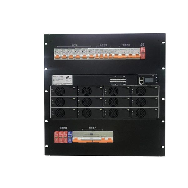
The panel box contains a series of circuit breakers or fuses that control the distribution of electrical energy to individual circuits throughout the building. An electrical panel box, also known as a breaker box or a distribution board, is a crucial component of any electrical system. It serves as a central hub for distributing electricity throughout a building, ensuring that power is delivered safely and efficiently to all the required locations. In this article, we'll explain what a series circuit is, how to draw a series circuit diagram, calculate. A distribution board or distribution box is where the main power supply is distributed to multiple loads. And all the switching and protective devices are installed in the distribution box. Single Phase Distribution Box generally consists of Double Pole MCBs, Single Pole MCBs, and RCCBs. Distribution. STEP 1: The flow of electricity begins at the g nerating station. at S the ation Switchyard. This is done to minimize the losses. STEP3: The ransmission Substation, increases the step-up voltage transformer from 69,000 to 765,000 volts. The distance it will go and the type of facilities distributed.
[PDF]
In this blog, we will explore the step-by-step process of using a beamsplitter cube effectively, along with some common applications that benefit from this powerful optical tool. Step-by-Step Guide on Using a Beamsplitter Cube. 📦 For purchasing, use the RP Photonics Buyer's Guide for beam splitters. It provides an expert-curated supplier directory, buyer-focused technical background information, and structured selection criteria to support professional procurement decisions. What are Beam Splitters? A beam splitter (or. An Optical Beamsplitter is an optic or optical device that is used to split a beam of light in two. Newport offers a wide variety of Beamsplitters in various shapes. It is a crucial part of many optical experimental and measurement systems, such as interferometers, also finding widespread application in fibre optic telecommunications. One beam is typically reflected while the other is transmitted. The ratio of reflected to transmitted light can vary based on the design of the beam splitter. Our plate beamsplitters have a coated front surface that determines the beam splitting ratio while the back surface is wedged and AR coated in order to minimize ghosting and interference effects.
[PDF]