Cable Trays* — Max two 24 in. (610 mm) wide by max 6 in. (151 mm) deep open-ladder cable tray with channel-shaped side rails formed of 0. 54 mm) thick aluminum or min 0. In practice, cable tray dimensions are a system of interrelated measurements —width, depth, length, and material thickness—that directly affect cable fill compliance, heat dissipation, structural loading, and long-term expandability. From an engineering standpoint, cable tray dimensions are not. Perforated Cable Tray System expertly constructed from high-grade stainless steel, offering exceptional durability and resistance to corrosion. With side height 100mm. A properly designed and installed cable tray system will provide. Studs — Wall framing to consist of wood studs or channel shaped steel studs. Wood studs to consist of nom 2 by 4 in. Additional studs shall be used to completely frame. Best Size: Here, deep trays (75mm to 150mm) are used since power cables are typically thick and heavy. Data cables, such as your Wi-Fi or computer ones, are extremely sensitive. They do not get hot; however, they do not like to hang or sag. In case a data cable folds in an excessive manner, the. ect the minimum bend ra-dius for cables as they exit the bottom of the cable tray. A rung spacing of 6 to 9 inches (150 to 230 mm) is preferable when the cable tray cont d for instrumentation and control applications that require additional protec eferred to support and protect numerous small.
[PDF]

A ladder type cable tray tee is a fitting used to create a branch in a cable tray system, allowing cables to be routed in three directions. Its "T" shape provides a secure and efficient way to split cables from a main tray into two separate paths, ensuring organized and flexible. A cable tray tee and tee cover are components used in cable management systems to support and protect electrical and data cables. Here's a brief explanation of each:. Rigid steel cable tray tee fitting with zero tangent, safety bottom, and full accessory support. ventilation to heat producing cable such as power communication and other with the same or different width of the cable run. All fittings are available in sizes and types corresponding to the straight cable tray sections. These fitting are including: elbow, horizontal cross, vertical inside. NOTE : Equal or un equal tees can be supplied. When ordering state widths W1xW2xW3.. Office: 147/22 Nguyen Sy Sach Street, 15 Ward, Tân Binh Dist, HCMC,VN. Is it possible to connect 2 cabletrays with a "branch piece (left picture)" instead of a "tee (right picture)". The tee has 3 connectors, the branch piece only has 1 connector. I would like to ajust the "Type properties -> Fittings -> Tee" with the branch family, but can't get it accomplished.
[PDF]

An Optical Splitter, also known as a beam splitter, is a passive optical device that divides a single input optical signal into two or more output signals. Conversely, it can also combine multiple signals into one. Knowing the difference between a splitter and an optical coupler helps you build better networks. You make your network work better when you pick the right device for each job. You can connect many users to one port with 1:n or 2:n splitters. By dividing a single optical signal from a central Optical Line Terminal (OLT) into multiple outputs for Optical Network Terminals (ONTs) at users' homes, splitters eliminate the need for dedicated fibers to each residence—slashing infrastructure costs while scaling network reach. This guide. In a Passive Optical Network (PON), a single optical fiber carries massive amounts of data using light. Signal Input: The fiber splitter receives the optical signal from the upstream network node and enters the splitter through the input fiber. Signal Distribution: Inside the splitter, according to the design structure and different. Splitters are passive optical devices that divide or combine optical signals, and they come in various types, including power splitters, uneven splitters, and wavelength-division multiplexing (WDM) splitters. Each type serves specific applications, enabling efficient use of optical infrastructure.
[PDF]

In this guide, I'll walk you through everything you need to know about choosing the right cable trays for your cables. Whether you're dealing with power cables, control cables, or communication cables, I'll break it down step by step. A 50 mm cable tray is used to organize and protect cable routes in industrial, commercial, and infrastructure facilities. This compact solution is suitable for power distribution lines, low-current systems, and engineering communications. Mirankul Group manufactures cable trays in Uzbekistan. Accessories for cable systems include a variety of different components necessary for the proper functioning of cable routes. They provide a structured and secure pathway for cables, ensuring organized installation and easy maintenance. Cable Trays are important for ensuring the protection of the wiring system and supporting insulated electric cables used for distribution and communication. Brilltech Engineers Pvt. Understand Your Cable Tray Requirements Before selecting a cable tray, consider the following key factors:. Selecting cable trays can feel overwhelming, especially with so many options available. But don't worry—I've got you covered.
[PDF]

Run the display transceiver [ interface interface-type interface-number | slot slot-id ] [ verbose ] command to view information about the optical module on a specified interface. In optical communication equipment, an optical module (Optical Module) contains several types of semiconductor chips that work together to complete the transmission and processing of optical signals. These chips typically include laser chips, photodetector chips, driver chips, transimpedance. When the optical module on an interface is faulty, you can run the display commands to view information about the optical module. Today, we will deeply analyze the four mainstream models of 100G QSFP28 dual-fiber optical modules: QSFP28-100G-SR4, QSFP28-100G-LR4, QSFP28-100G-ER4 and. The following uses the Moduletek SFP-10G-LR module connected to a Huawei S6700 switch as an example to introduce how to read information of the connected optical module on a Huawei switch. Figure 1 Schematic Diagram of Optical Module Connected to Switch 1. Optical Module Status Check Run the. Upgrade to 100G or 400G optics and save. Cisco Transceiver Modules - Learn product details such as features and benefits, as well as hardware and software specifications. Network administrators have a major challenge determining the right Cisco SFP modules, understanding complex model numbers that directly affect network performance and stability.
[PDF]
A junction box contains two trade size 3 raceways on the left side and one trade size 3 raceway on the right side. raceway on the right side, and one 3-in. raceways on. Pull boxes, junction boxes, and conduit bodies must be sized to allow conductors 4 AWG and larger to be installed without damage to the conductor insulation. The NEC provides sizing requirements in 314. Keep in mind these requirements address conductors used for general wiring, such as those. Article 370 covers the installation and use of all boxes (and conduit bodies) used as outlet, junction, or pull boxes, depending on their use. You're reading an older article from ELECTRICAL CONTRACTOR. Some content, such as code-related information, may be outdated. Visit our homepage to view the. When conductors enter an enclosure with a removable cover, such as a conduit body or wireway, the minimum distance from the raceway entry to the removable cover is the bending distance listed in Table 312. 6 (A) for one conductor per terminal [314. This approach helps in the safe organization of wires. To stop a fire from beginning or spreading, sparks are contained by fireproof connections and boxes. In this reading, we will delve into the definition of a. For example, a box is needed for eight 2-inch conduits. Each conduit will contain 2/0 conductors that will be spliced within the box. What is the minimum length required for the left/right (“X”) dimension? The minimum distance required because of the.
[PDF]

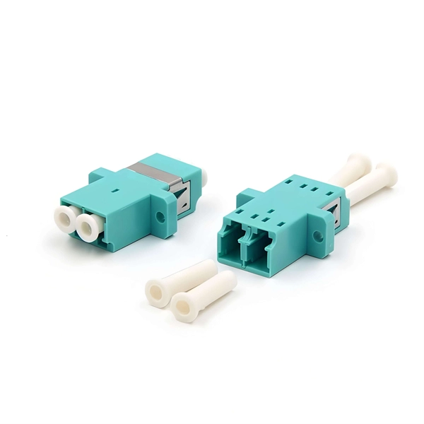
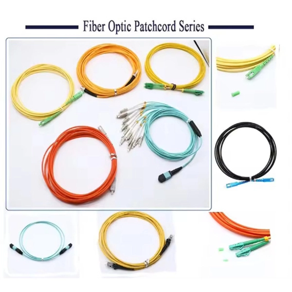
In this post, we'll walk you through practical tips, essential tools, common pitfalls, and the techniques that will help you get your fibre patch cable installations right the first time. Correct patch-cord installation is essential for maintaining low insertion loss, stable return loss, and long-term reliability in both indoor and outdoor fiber networks. Proper handling, routing, cleaning, bend-radius management, and connector alignment ensure that the optical link meets design. Proper connection of fiber optic cables is essential to harness these benefits fully, as even minor errors can lead to significant performance issues like signal loss. This guide addresses expert-certified best practices applied by professionals in the telecommunications, data. Yingda outlines the tools and materials needed to install fiber optic patch cords, as well as a complete step-by-step installation guide and important safety considerations to take. We will also tie this procedure back to the earlier discussion of multi-mode fiber types (OM1 to OM5) and connection. The Flex-Angle boot is designed to bend any angle or direction from straight to 90°. OMC flex angle boots for LC&SC fiber optic connectors are available on any single-mode or multimode patch cord. They are designed so the installer can pre-bend the boot into any direction or angle. Selecting the correct fibre patch lead is crucial for optimising signal performance and.
[PDF]

Diagram showing positive tip polarity on the left and negative tip polarity on the right. To read diagram: The center positive drawing on the left indicates that the center (also known as the tip) of the output plug is positive (+) and the barrel (ring) of the output plug is negative. The center positive drawing on the left indicates that the center (tip) of the output plug is positive (+) and the barrel of the output plug is negative (-). Symbol for a center-positive power supply. It is always good practice to test. The term positive terminal describes which of the two connection terminals on direct current (DC) equipment supplies or is meant to receive a positive electrical charge. DC power supplies always feature a positive to negative electron flow and always have a negative and positive terminal. Polarity. It is defined by the positive and negative terminals of a power source, such as a battery. Understanding polarity is essential because connecting a device to a power source with the correct. The rating plate of an Extra Low Voltage Power Supply (ELVPSU) shows various symbols and abbreviations. These represent critical information about the supply's ratings, class, polarity, and other safety details. The polarity symbol indicates if the centre (or tip) of the output plug is positive (+).
[PDF]

How to design required reinforcement for RC core walls in Robot Structural Analysis. Use workflow similar to RC slab required. and roof systems in concrete buildings and parking structures. The cross section of this type of precast concrete member is economical and ef-ficient because it uses ess concrete due to continuous voids (cores) along the length. With the reduced cross-sectional area at middepth, the member. although for buildings over 49 m (160 ft), IBC 2006 requires use of a dual system. Use of nonlinear response history analysis (NRHA) coupled with peer-review has become a common way to assess the expected performance of tall buildings at various hazard levels to avoid the use of a backup Special. Reinforced concrete core walls with open sections are commonly used in practice as a lateral load resisting system for multi-storey buildings. This type of walls has mainly been modelled in the past using simplified models such as plastic hinge models or equivalent frame models. Such models are.
[PDF]
Available in both single-mode (9/125) and multimode (50/125) options, Aerial Fiber Cable ensures stable attenuation over long distances, supports high-bandwidth transmission, and offers flexible strand count options (from 2 to 48 cores). Founded in 1984, AFL is an international manufacturer providing end-to-end solutions to the energy, service provider, enterprise, hyperscale and industrial markets. AFL's products are in use in over 130 countries and include fiber optic cable and hardware, transmission and substation accessories. AFL offers a complete portfolio of fiber optic cable, supporting hardware and compression accessories that are designed to meet the most demanding transmission and distribution environments. As the leading world manufacturer of fiber optic cable, AFL is uniquely positioned to provide a full line of. Aerial cables are suspended from poles or pylons or mounted on buildings. Some are self-supporting, requiring no separate messenger wire between poles to support the cable's weight. Already Know What You Are Looking For? Already have your cable in mind? Visit all our outdoor cables here. Ribbon. An aerial fiber optic cable is an insulated cable usually containing optical fibers required for a telecommunication line, which is suspended between utility poles. Because aerial cables are exposed to harsh outdoor environments and extreme weather conditions, their materials must be strong and durable.
[PDF]
Mouser ofrece inventarios, precios y hojas de datos para Fibra óptica. Sourcing managers and procurement leaders use Volza's Company Profiler to analyze shipment volumes, trade routes, and buyer distribution—helping them assess supplier scale, reliability, and long-term partnership potential for risk-mitigated, confident procurement decisions. Volza's Fiber Optic. The Americas Region Caribbean Optical -Ring System (ARCOS-1) is a 8,700 km submarine cable system connecting 24 landing points in 15 countries, including the United States, the Bahamas, the Turks and Caicos Islands, the Dominican Republic, Puerto Rico, Curacao, Venezuela, Colombia, Panama, Costa. The Guatemala Fiber Optic Cable Market is projected to witness mixed growth rate patterns during 2025 to 2029. The growth rate begins at 8. 14% in 2025, climbs to a high of 8. By 2027, Guatemala's Fiber Optic Cable market is forecasted to achieve a growing.
[PDF]

Professional-grade cantilever support arm specifically designed for cable tray installations. Features a welded flat mounting plate construction for secure attachment. Manufactured by nVent CADDY, this sturdy support solution provides reliable cable management infrastructure. 0 are currently in. 15. 41x21mm horizontal support for wall fixing of cable trays, electrical conduits and other heating pipe installations, A/C, fire protection systems, etc. Excellent loading capacity. Robust and secure system. Made of steel, available in various protection systems. Available in widths from 100 to 1000. Cable Support Systems are well designed to provide necessary support for cable trays, cable ladders and trunkings. Cable supports are manufactured according to common standards from high quality raw materials. Requires only one bolt for quick fixing and is used with open face at the top. Two bolt. us-trations without notice. All illustrations, descriptions and technical information included in this document are provided as indications and can cable trays are equivalent. The mechanical and electrical characteristics, tests, certifications, overall quality management, recommendations mentioned.
[PDF]