Here, to overcome this challenge and achieve high-sensitivity temperature sensing in a high-temperature environment, we propose a new type of temperature FPI sensor by inserting and sealing a section of Cr20Ni80 metal microwire inside a section of a silica hollow core. Here, to overcome this challenge and achieve high-sensitivity temperature sensing in a high-temperature environment, we propose a new type of temperature FPI sensor by inserting and sealing a section of Cr20Ni80 metal microwire inside a section of a silica hollow core. Fiber optic interferometers to sense various physical parameters including temperature, strain, pressure, and refractive index have been widely investigated. They can be categorized into four types: Fabry-Perot, Mach-Zehnder, Michelson, and Sagnac. In this paper, each type of interferometric sensor. These are reliable and easy-to-use devices that have high power, can automatically adjust to real-time conditions, and have a straightforward display that eliminates any guesswork. This series is able to detect virtually anything, in any environment with high power and a variety of head options. Even though many of the devices show temperature-, strain-, and pressure-sensitivity, we focus our review on refractive index.
[PDF]

This is a simple video showing how to install a 850nm fiber optic link using SFP transceivers between 2 10 Gigabit backbone switches. Covers transceiver inst. As a leading provider of fiber optic solutions, Weunion offers a wide range of SFP-compatible products, including optical transceivers, DAC/AOC cables, LC patch cords, and MPO/MTP assemblies. This guide explores the essentials of SFP connectivity, installation best practices, and how Weunion's. These transceiver modules are hot-swappable input/output (I/O) devices that plug into 100BASE, 1000BASE and 10GBASE ports (for SFP+), which connect the module port with the fiber-optic or copper network. This document contains these sections: The SFP transceiver modules are hot-pluggable I/O. An optical module is an optoelectronic conversion device that transmits data by converting electrical signals into optical signals. Common types of optical modules include SFP, SFP+, SFP28, QSFP, QSFP28, etc. Different types of optical modules have different performance parameters such as speed. The 1310 nm WWDM solution, 10GBASE-LX4, requires the use of a mode-conditioning patch cord on multimode fiber to achieve its specified range of operating distances. more Audio tracks for some languages were automatically generated. Learn more This is a simple. One of the most widely deployed optical solutions for short-distance 10G links is the multimode SFP+ transceiver, commonly referred to as a 10GBASE-SR module.
[PDF]
A neat, well-organized subpanel bundles wires to conserve space and improve access. Ideally, wire groups are installed in layers and wires are bent at right angles to buses or breakers. Label short sheathing sections (slugs) to indicate which circuits wires serve. Choose the right box based on environment (indoor/outdoor), load capacity, and durability. Check for proper IP/NEMA ratings and material quality. Ensure safe placement: install in. Welcome to this live training session! ⚡ In today's tutorial, I'll be demonstrating how to arrange cables neatly inside a distribution bo. more See what others said about this video while it was live. Wire color: The neutral wire is blue, and the color of the phase wire (A phase is yellow, B phase is green, and C phase is red). It consists of various protective and control devices for electricity distribution in a building. 📌At the top, there are main circuit breakers and residual current devices (#RCDs), which protect against overcurrent and leakage currents. 📌The middle section includes an electric energy meter that. Wiring distribution panels serve as the central hub and nerve center, routing power from the main service feed to multiple circuits. When setting up such a significant component of industrial, commercial, and utility applications, it's essential to get everything right. When wiring distribution.
[PDF]

Wiring Direction: Wiring between the main circuit breaker and each branch circuit breaker in the box generally goes on the left, and the wiring out of the distribution box generally goes on the right. Binding Requirements: The wires should be bound with. Learn how to wire a distribution box step by step! This video shows real on-site footage of electrical installation, demonstrating safe and standardized wiring methods used by professionals. Whether you're a professional or a DIY enthusiast, understanding the correct procedure can prevent accidents and ensure optimal performance. This guide provides step-by-step. Hey, in this article we are going to see the Single Phase Distribution Box Wiring Diagram and Connection Procedure. A distribution board or distribution box is where the main power supply is distributed to multiple loads. Students utilize various electrical components, including circuit breakers and cables, and are guided to apply. Correct wiring methods for circuit breakers within distribution boxes are fundamental to ensuring electrical safety and compliance with established codes. The distinction between 1P and 2P circuit breakers plays a pivotal role in determining the appropriate protection level for various circuits. Connection method: Each switch takes a wire from the incoming point and connects it to the incoming end of the switch, or uses parallel connection to reduce the difficulty of wiring.
[PDF]
Professional quotes from experienced fiber optic cable installation contractors are crucial for accurate project estimates, as the costs of fiber optic cabling can vary significantly based on location, terrain,.
[PDF]
The soft starter wiring diagram typically includes information about the power supply, motor connections, control circuit, and bypass arrangement. It helps in understanding the complete wiring arrangement and makes it easier to troubleshoot any potential issues. See Technical Data TD03900001E. We are guided by our commitment to do business right, world's most urgent power management challenges. A proper wiring diagram is crucial to ensure the soft starter functions effectively and protects the motor from any kind of damage. Whether you're a professional electrician or a DIY enthusiast, this detailed wiring diagram and installation guide will help you understand the c. more. Soft starters are widely used to reduce the current surge when devices are started and to provide ramped acceleration to motors. The use of soft starters can reduce energy costs by up to 15%, as well as providing protection from damage caused by voltage sags or electrical faults. Connecting the soft starter to a wye motor inserts the SCRs directly in the line wiring, referred to as "In Line" wiring. If the motor is hard. If you're looking to install a soft start system in your electrical setup, it's crucial to understand the wiring diagram that goes along with it. A soft start system is designed to gradually increase the voltage and torque to a motor, reducing the initial inrush current and protecting both the.
[PDF]

Cable Trays* — Max two 24 in. (610 mm) wide by max 6 in. (151 mm) deep open-ladder cable tray with channel-shaped side rails formed of 0. 54 mm) thick aluminum or min 0. In practice, cable tray dimensions are a system of interrelated measurements —width, depth, length, and material thickness—that directly affect cable fill compliance, heat dissipation, structural loading, and long-term expandability. From an engineering standpoint, cable tray dimensions are not. Perforated Cable Tray System expertly constructed from high-grade stainless steel, offering exceptional durability and resistance to corrosion. With side height 100mm. A properly designed and installed cable tray system will provide. Studs — Wall framing to consist of wood studs or channel shaped steel studs. Wood studs to consist of nom 2 by 4 in. Additional studs shall be used to completely frame. Best Size: Here, deep trays (75mm to 150mm) are used since power cables are typically thick and heavy. Data cables, such as your Wi-Fi or computer ones, are extremely sensitive. They do not get hot; however, they do not like to hang or sag. In case a data cable folds in an excessive manner, the. ect the minimum bend ra-dius for cables as they exit the bottom of the cable tray. A rung spacing of 6 to 9 inches (150 to 230 mm) is preferable when the cable tray cont d for instrumentation and control applications that require additional protec eferred to support and protect numerous small.
[PDF]
Free electrical calculators for wire sizing, voltage drop, load calculations, conduit fill & power factor. NEC compliant tools for electricians & engineers. In this guide, we'll break down everything you need to know to install a distribution box correctly and confidently. Choose the right box based on environment (indoor/outdoor), load capacity, and durability. Check for proper IP/NEMA ratings and material quality. Ensure safe placement: install in. Professional electrical wire sizing tool based on National Electrical Code (NEC) standards. Calculate proper wire gauge, voltage drop, and ampacity for safe electrical installations. Input your electrical parameters to get accurate wire size. Pro Insight: A well-planned distribution box feels like a silent partner—you only notice it when something's wrong. Our goal? Make sure you never notice it. Before we dive into calculations, let's get familiar with a few essentials: 1. Create accurate bids and win more projects with automated formulas. The sizing requirements for pull boxes, junction boxes, handhole enclosures, and conduit bodies exist to prevent conductor insulation damage. Those requirements are in 314. 28, and they apply to all conductors 4 AWG and larger (Fig. To illustrate how these requirements prevent conductor. Estimate wire ampacity with derating factors for temperature and conduit fill. Reference tool based on NEC guidelines. It is NOT a substitute for professional.
[PDF]
Check out our chain link frames selection for the very best in unique or custom, handmade pieces from our wall hangings shops. Check each product page for other buying options. Price and other details may vary based on product size and color. Made of rust-resistant solid brass, it is a decorative and more sturdy alternative to standard cord options. Ideal for new construction, or for replacing a worn or damaged system. Our Number-25. 24 Pack: Steel Galvanized Wire, 100ft. Firmly attach pictures and art to your walls using frame and wire-hanging materials from Michaels. This set of 9 hanging frames is an excellent blend of practicality and aesthetic design, which is crafted to enhance your display needs across various settings. Whether used in homes, offices, or commercial spaces, these frames offer a sleek and sophisticated way to showcase your pressed flowers. Shop our complete gallery hanging system selection, including wall-mounted and picture rail hanging system options. A 9" round flue cover with a linked chain frame and hanger with a picture of a woman dressed in clothes from the Victorian era. Misc 1680 Peach Thermoset Lucite or Moonglow Cabochons with Scored C Shaped Frames. Bracelet Alpaca cuban link chain Jewelry Making Craft. Christian Dior 90s vintage oval.
[PDF]

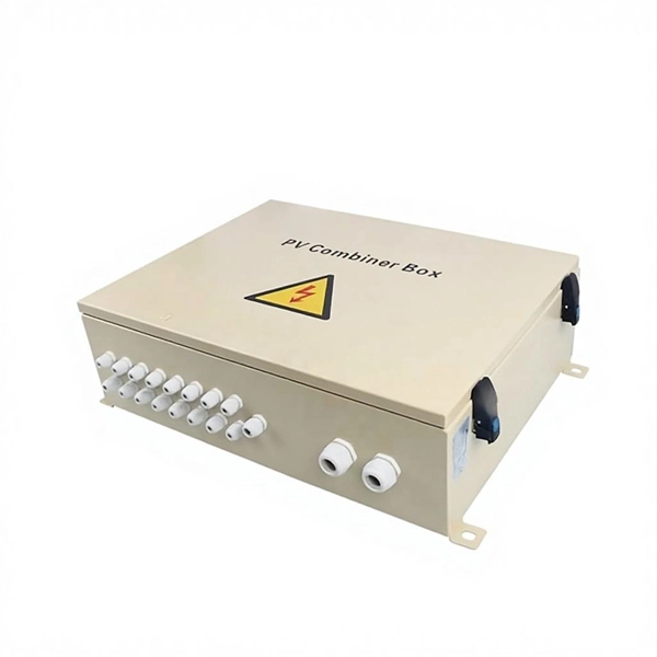
99 after $25 OFF your total qualifying purchase upon opening a new card. Return this item within 90 days of purchase. Present an elite addition to your outdoor space with this VEVOR PV Combiner Box with Rated Current Fuse Circuit Breaker Lightning Arreste Connector. Lightning strikes pose a critical risk to photovoltaic systems, with 23% of solar farm failures traced to electrical surges according to 2023 NREL data. For engineers and project managers, selecting the right photovoltaic combiner box with integrated lightning protection isn't just optional – it's. A clear wiring diagram helps installers understand the flow of current from each string to the main DC bus, making the system safer and easier to maintain. For systems with three or more DC strings, using a solar combiner box is recommended according to international PV safety standards such as IEC. PV combiner box function: PV combiner box tidied up connection and confluence of photovoltaic modules. It is used to reduce the connection of the photovoltaic array to the inverter and optimize the system structure. Make it easy to cut off the circuit in maintenance and reduce the scope of the power. Pay $44. EKDB-PV4/1-M IP65 DC string box is designed for 4 string PV system, for surge protection and over-load protection at solar DC side.
[PDF]

We will look at how to interpret PLC LED status indicators for digital inputs and outputs and how to perform troubleshooting tests using a Digital Multimeter. This section includes the block diagram of the DI 16x24VDC ST module with the terminal assignments for a 1-wire connection. Information on wiring the BaseUnit can be found in the system manual ET 200SP distributed I/O system. The load group of the module must begin with a light-colored BaseUnit. How to wire real-world signals into the Logo's digital inputs to detect whether a machine is running. Covers stack lights, door sensors, relay contacts, and proximity switches — with a complete wire diagram and step-by-step instructions for both electrical engineers and IT teams. You have a Siemens. PLC and DCS control systems Wiring Diagrams for Digital Input (DI), Digital Output (DO), Analog Input (AI), and Analog Output (AO) signals. be responsible or liable for indirect or consequential damages resulting from the use or application of this equipment. The examples and diagrams in this manual are included solely for illustrative purposes. Because of the many variables and requirements. This manual contains information that is necessary to use the NX-series Digital I/O Unit. PLC programs rarely cause failures, so in this article, we'll assume that there are no program errors and that the fault originates in the.
[PDF]
The 11-in-1 Screwdriver includes the 8 bits and 3 nut drivers most requested by professionals. The bit prevents bit wear from hardened screws and extends bit life when fastening specialty screws found in elec.
[PDF]

This publication shows how to wire and install the 4010-9825 24V Distribution Block into a 4010 Fire Alarm Control Panel (FACP). Refer to the 842-058 Field Wiring Diagram for additional wiring information. 1 Transformer connection: Two red wires connect to AC 220V input port, while two yellow wires connect to AC input port of main board (had connected by the factory. 2 DC12V battery connection: Red wire on the circuit main board connects to the positive pole of acid-lead battery while black. Notify the carrier and call Telect's Customer Service Department at 1-800-551-4567. Keep the container until you have checked equipment operation. Use the original, undamaged container if you are instructed to return. Learn how to wire a distribution box step by step! This video shows real on-site footage of electrical installation, demonstrating safe and standardized wiring methods used by professionals. Such a system, however, does not assure. Material preparation: Prepare the required circuit breakers, wires, wiring ties and other materials, and ensure that they meet the design drawings and installation requirements. Location determination: Determine the installation position of the circuit breaker according to the position of the.
[PDF]

Whether you're an electrician or a DIY enthusiast, this tutorial will help you understand the fundamentals of wiring a distribution box for a residential setup. The diagram of the distribution board's wiring shows exactly how each circuit is wired and connected. What is Distribution Board? Distribution board. A distribution box is the heart of any electrical system. It takes the incoming power and safely distributes it to different circuits throughout your building. Whether in a home or an industrial facility, this box keeps your electrical setup organized, functional, and efficient. However, the key to. In this guide, we will break down the key elements involved in connecting the main power supply to your home, providing a clear path for a successful setup. We will focus on the critical parts of the system, from basic components to step-by-step assembly procedures. It serves as a central hub for distributing electricity throughout a building, ensuring that power is delivered safely and efficiently to all the required locations.
[PDF]

The complete process for terminating cable runs at a patch panel, from mounting and cable management to punch-down, labeling, and testing every port. To wire a patch panel: Mount the panel in your rack. If you're still deciding which panel style fits your site (keystone vs punch‑down vs pass‑through), start with How to choose a patch panel and come back here once the hardware is locked in. 60-second answer If you want reliable results, the winning recipe is simple: keep pair twists tight right up. Network patch panel, cable manager, network cable, wire stripper, crimping tool, zip ties. Use a small yellow tool or wire stripper to remove the outer jacket of the network cable. Cut off the cross-shaped skeleton of the Cat6 patch cord. Insert. Patch panels make cable management and network organization very easy over long periods of time, but you'll need to wire the panels in order to put them into your network. Not to worry, this guide will walk you through the whole process. Before you jump into the task, ensure that you have the. Testing a patch panel is an essential task to ensure the reliability and efficiency of a network infrastructure. The process verifies the end-to-end connection, ensuring the cable is properly terminated at the wall jack and at the distribution point, such as a switch or patch panel.
[PDF]