First, inspect the optical module appearance for physical damage, cracks, missing components, poor solder joints, or burn marks. Next, compare voltage, resistance, and waveform parameters between a normal it and the suspected faulty one, both in powered and unpowered states. As core components of optical communication systems, the proper installation and use of optical modules directly impacts network stability. This article systematically identifies common anomalies during optical module installation. However, during installation and daily operation, various issues may arise. The following will introduce the causes of various problems and how to deal with them. Optical module method/step 1. During the test, the value of the module I BiasADC is 0, and the TXLOP-ADC and. These compact devices convert electrical signals to optical signals and vice versa, enabling data transmission over fiber optic cables. While generally reliable, failures do occur, leading to frustrating downtime, performance degradation, and costly troubleshooting. This comprehensive guide details. Have you ever dealt with sudden network drops from faulty optical modules? Issues like this cannot only break communications, but they can really jeopardize business continuity.
[PDF]

While fiber optic cables are typically installed within conduits alongside the pipeline, there are significant challenges to installing the conduits along trenchless installations, such as horizontal directional drills (HDD). The typical method. While fiber optic cables are typically installed within conduits alongside the pipeline, there are significant challenges to installing the conduits along trenchless installations, such as horizontal directional drills (HDD). The typical method utilized for HDD conduit installation is to attach a coated stainless steel conduit to the pullheadof the. Fiber optics can help monitor pipeline performance based on subtle "tone” changes. Fiber optic monitoring detects differences in vibration, temperature, sound, and strain. Any change in the frequencies allows pipeline operators to see there are issues in the line. As there is no electrical power required to use the cable, it is the safe choice for. CCIhas installed and tested several different design modifications to the TIPS model. All have been generally successful, but small upgrades and improvements have built the version that is currently in use. The resin, fiberglass, and polymer casings providing strength and protection to the 0.5” stainless tubulars all add reassurances the product wi.
[PDF]
For a basic plastic D-box, expect $25-$60 per unit, with installed costs typically $150-$400 depending on site access and labor rates. Heavier-duty or multi-zone configurations can push total to $600-$1,000 for the box and labor, while complex installations or off-grid sites. Buyers typically pay a wide range for septic distribution box replacement, with cost driven by box material, accessibility, and local permitting. This guide outlines typical price ranges, how costs break down, and regional differences to help homeowners budget accurately. The price is driven by box type, piping connections, and the need for trenching or backfilling. This guide provides a clear cost range in USD with practical budgeting tips and per-unit. Homeowners often pay for a distribution box (D-box) as part of a septic system upgrade or replacement. Cost ranges reflect box price plus. Distribution box cost encompasses various factors that influence the overall investment in electrical distribution systems. The cost is driven by box size, material, and installation requirements, with price ranges reflecting basic plastic units up to heavier-duty or re-locatable options. The following. While distribution box prices depend heavily on capacity and features, we've tracked emerging patterns. Expect these price points when budgeting for 2025 installations: Quality power cables make or break your electrical system. Modern copper-aluminum hybrids offer conductivity at lower cost while.
[PDF]
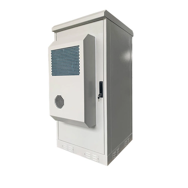
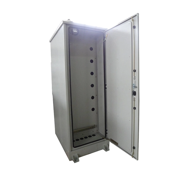
Whether upgrading an aging electrical panel or setting up your facility, this guide will walk you through the critical steps to installing an MCB Distribution Box safely. Strictly speaking, the word “Distribution Box (D-box)” can refer to two categories: electrical distribution boxes and septic tank distribution boxes. This article mainly talks about the first one. An electrical distribution box, also known as a power distribution box, panelboard, or consumer unit. These extras help make the box easier to install and maintain. Choosing the right distribution box isn't one-size-fits-all. You need to consider where it will be used, how much power it needs to handle, and how well it's built to last. Let's go through what matters most. Whether it is residential buildings, commercial facilities or industrial sites, the. This guide provides step-by-step instructions for connecting a distribution box and highlights key factors to consider during installation. It serves as a. Learn how to wire a distribution box step by step! This video shows real on-site footage of electrical installation, demonstrating safe and standardized wiring methods used by professionals.
[PDF]

Fiber optic loss calculation formula: Total link loss (LL) = Cable attenuation + Connector attenuation + Fusion attenuation [Note: If there are other components (such as attenuators), their attenuation values can be added]. Intrinsic Optical Fiber Losses comprise of absorption loss, dispersion loss and scattering loss caused by the structural defects. The detailed information about these optical losses and how to reduce them are. Calculate fiber optic signal loss based on cable length, attenuation, and connector losses. Determine cable loss, connector loss, and total system loss in decibels (dB) to assess signal quality and repeater requirements. Fiber optic loss is calculated in two parts: cable loss and connector loss. This calculator determines fiber loss based on input power, output power, and the length of the fiber optic cable. In summary, fiber optic loss is. Use this worksheet to input values for all variables that will impact your system's performance. After entering your values, please ensure you click the 'Calculate Link Loss' button at the bottom of the page to generate your total link loss. This step is necessary to see if your system falls within. Optical fiber loss is a term for signal loss affecting transmission reliability. Optical fiber loss is.
[PDF]
Find the latest exports, imports and tariffs for Optical fibres and cables trade in Vanuatu. How does 6W market outlook report help businesses in making decisions? 6W monitors the market across 60+ countries Globally, publishing an annual market outlook report that analyses trends, key drivers, Size, Volume, Revenue, opportunities, and market segments. This report offers comprehensive. CRU provides comprehensive, accurate and up-to-date price assessments and research reports for bare optical fibre across various key regional markets, combined with insights into the factors and events affecting markets.
[PDF]
It emphasizes the importance of considering mechanical and environmental aspects, referring to the IEC 60794-2 series for technical specifications. The document details the characteristics of optical fibers and cables, including transmission, microbending and macrobending. Nowadays, optical communications are the most requested and preferred telecommunication technology, due to its large bandwidth and low propagation attenuation, when compared with the electric transmission lines. Besides these advantages, the use of optical fibers often represents for the telecom. As environments are becoming increasingly harsh, the ability of optical fiber cable to withstand such environments is of the utmost importance to outside plant users. Laboratory accelerated aging environments have long been used as a measure to predict field performance of optical fiber and cables'. This study investigates the strain transfer mechanism for different types of fiber optic cables while embedded in concrete cubes, sustaining a boundary condition which features a displacement discontinuity. The strain transfer mechanisms for different cables are compared under increasing strain. This document outlines the recommendations for single-mode optical fiber cables used in telecommunication networks within buildings, focusing on their mechanical and environmental characteristics. It specifies that these cables must comply with standards such as ITU-T G.
[PDF]