
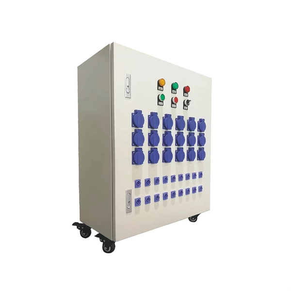
Ensuring Uninterrupted Power Supply: A UPS and DG monitoring system plays a vital role in ensuring uninterrupted power supply. It continuously monitors the power sources, batteries, and overall system performance. A UPS system provides temporary power during electrical outages or disturbances, acting as a bridge until the primary power source is restored or the DG system takes over. They are designed to deliver power instantaneously from energy stored in batteries, super capacitors, or a mechanical storage method. Sensitive electronics, such as computers. UPS or Uninterruptible Power Supply is vital protection against loss of data and costly hardware damage. It ensures that the network systems are operational when the main source of power fails. For home users, a UPS can protect desktop PCs, gaming consoles, and smart home devices from unexpected power cuts. In business settings. These monitoring devices, commonly known as RTUs, will send alerts back to vital personnel via LAN, phone voice message, serial connection, T1, fiber, or other available transport. In this way, organizations can track and log the voltage at the cell level, providing a good assessment of the overall. A 24V DC UPS can manage voltage fluctuations, frequency distortions. These short outages and provide a clean and reliable supply to the control system. With its backup battery pack, a DC UPS designed for an industrial environment will be more resistant to harsh external conditions.
[PDF]
Pricing (CAD) Filter the results in the table by unit price based on your quantity. Fiber Optic Connectors are available at Mouser Electronics. Mouser offers inventory, pricing, & datasheets for Fiber Optic Connectors. Mouser is an authorized distributor for many fiber optic connector manufacturers including Amphenol, Broadcom, Glenair, Molex, Neutrik, Radiall, TE Connectivity & more. More. Explore high-performance connectivity solutions for military drone systems, including antennas, fiber optics, RF connectors, and cable assemblies designed for reliable UAV and base station communications. Whether you are setting up a new network or upgrading an existing. FTTR (Fiber to the Room) networks rely on high-performance optical fibers to deliver ultra-fast, reliable connectivity directly into individual rooms of homes or commercial buildings. The choice of fiber type significantly impacts bandwidth, distance capability, durability, and installation. INNO Instrument – Hexatronic Canada is the Authorized distributor for Inno Instrument fiber optic splicing and test equipment across Canada. Inno Instrument was founded in 2007, and its main business area is manufacturing of fiber optic splicing equipment, test equipment and accessories.
[PDF]
Coarse wavelength-division multiplexing (CWDM), in contrast to DWDM, uses increased channel spacing to allow less sophisticated and thus cheaper transceiver designs.OverviewIn, wavelength-division multiplexing (WDM) is a technology which The. A WDM system uses a at the to join the several signals together and a at the to split them apart. With the right type of fiber, it is possible to have a device that does both s. Originally, the term coarse wavelength-division multiplexing (CWDM) was fairly generic and described a number of different channel configurations. In general, the choice of channel spacings and frequency in these co. Dense wavelength-division multiplexing (DWDM) refers originally to optical signals multiplexed within the 1550 nm band so as to leverage the capabilities (and cost) of EDFAs, which are effective for wavelengths between ap. 's Enhanced WDM system is a network architecture that combines two different types of multiplexing technologies to transmit data over optical fibers. EWDM combines 1 Gbit/s Coarse Wave Division Mu. Shortwave WDM uses (VCSEL) transceivers with four wavelengths in the 846 to 953 nm range over single OM5 fiber, or two-fiber connectivity for OM3/OM4 fiber. Transceivers Since communication over a single wavelength is one-way (simplex communication), and most practical communication systems require two-way (duplex communication) communication, two wavele.
[PDF]
Epson Device Admin is an application that allows you to install devices on the network, and then configure and manage the devices. The following outlines the main features. A complete multi-vendor reference for GPON/EPON OLT configuration, monitoring & troubleshooting. This repository serves as a technical knowledge hub for network engineers working with FTTH (GPON/EPON) infrastructure. It contains configuration commands, troubleshooting methods, power-check commands. Streamline configuration and management for your Epson printer fleet. With automatic device discovery, this intuitive software helps save. OpManager monitors ZTE-ZXPON-EPON-ONU for health and performance. With the help of our ZTE-ZXPON-EPON-ONU device template, you can easily discover and monitor critical performance metrics without any hassle. This guide dives deep into EPON technology, its benefits over alternatives like GPON, and the critical role of optical modules. Whether you're a network engineer or a tech. This document provides examples of configuring Ethernet Passive Optical Network (EPON). The configuration examples in this document were created and verified in a lab environment, and all the devices. Versatile dual-layer tester purpose-built for PON service activation, with added broadband capabilities. The PPM1 leverages a unique patented technology that makes all the difference in the field.
[PDF]

Use the SWD or JTAG interface to connect the ST-Link v2 to the STM32 microcontroller. Download and install STM32CubeIDE or another compatible IDE. Install the ST-Link USB driver (available on the STMicroelectronics. The ST-LINK/V2 is an in-circuit debugger/programmer for the STM8 and STM32 microcontrollers. The single wire interface module (SWIM) and the JTAG/serial wire debugging (SWD) interfaces facilitate communication with any STM8 or STM32 microcontroller operating on an application board. ATOLLIC, IAR and KEIL Integrated Development Environments for. How do you use SWD (Serial Wire Debug) for debugging STM32? - HackMD Using SWD (Serial Wire Debug) for debugging STM32 microcontrollers is a powerful way to monitor and control code execution, inspect registers, and analyze faults. Here's a step-by-step guide to set up and use SWD effectively: 1. In addition. This small guide will explain how to connect your debugger to your development board. There are two commonly used connectors which expose only the SWD (Serial Wire Debug) interface or the full JTAG interface. If you are using one of ST's official Nucleo or Discovery boards, you do not have to. To upload a program to a chip from Thomson Semiconductor you need an ST-Link programmer device to connect your PC. Thompson sells branded programmers, adaptors and cables. We'll use an inexpensive ST-LinkV2. They look like AVR programmers but you need to read the pinouts on the side.
[PDF]
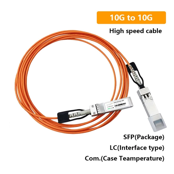
Below are eight SFP-based choices commonly used in tunnel monitoring, traffic analytics, and roadside IP cameras. Each item includes the key specs that matter in the field, a best-fit scenario with realistic numbers, and quick pros and cons. GigaVUE ® TA Series, part of the Gigamon Deep Observability Pipeline, aggregates traffic from SPAN/TAPs to deliver pervasive edge visibility. Supporting speeds from 1G to 400G, it improves monitoring efficiency and reduces costs through core intelligence and GigaVUE-OS. The GigaVUE TA Series is. An Aggregation or "Top-of-Rack" switch is designed to connect everything in a rack at high speeds, then have an even bigger pipe out to the rest of the network. The Pro Aggregation does this with it's SFP28 25Gbps ports. The regular Aggregation switch is best used to connect all devices in a rack. What Is an Aggregation Switch? An aggregation switch is a network device that consolidates traffic from multiple access switches, wireless access points, or other edge devices and forwards it to core switches or routers. By bundling multiple network connections into a single high-bandwidth link. We'll be happy to answer all of your technical, pricing & availibility questions. Road monitoring deployments live or die by link stability: vibration, temperature swings, moisture, and long fiber runs can turn a “works on the bench” SFP into a field failure.
[PDF]
This system enables tracking of the presence and relative intensity of multiple wavelength-division-multiplexed (WDM) data streams that span over a broad frequency band with high resolution, accuracy, and fast measurement update rates. In fiber-optic communications, wavelength-division multiplexing (WDM) is a technology which multiplexes a number of optical carrier signals onto a single optical fiber by using different wavelengths (i., colors) of laser light. This allows multiple channels of data to be transmitted simultaneously. Typically ships in 21 day (s) Actual lead time confirmed upon receipt of order. EDGE HD-DWDM modules incorporate LC APC connections on single fiber ports and MDC APC connections on two-fiber output channel pairs. 6i, 12i and 24i modules are used for the initial channels deployed, while 12u and 24u. Wavelength Division Multiplexing increases fiber capacity by combining (mux) and separating (demux) multiple input channels over a single fiber output. This guide delves into the principles, types, applications, and future trends of WDM. Tailored for professionals sourcing solutions from CommMesh, it. We propose a novel (to our knowledge) and simple real-time optical monitoring (RTOM) system for dynamic spectral analysis of telecommunication signals, involving electro-optic (EO) temporal sampling followed by dispersion-induced frequency-to-time mapping and high-speed photodetection.
[PDF]

The operation and skills of fiber optic fusion splicing technology can be mainly divided into five steps: fiber stripping, fiber cutting, fiber melting, fiber sleeve, and fiber winding. Two types of splices are used in fiber optic cabling one is Mechanical the other is Fusion. And tools used for fiber fusion: fusion splicer; fiber cleaver; cable stripper; fiber optic stripper; alcohol;. These specialized devices are engineered to manipulate, terminate, join, and verify light-carrying strands without introducing microscopic fractures or contamination. At Weunion, we categorize these essential instruments into four primary operational phases: Preparation: Removing protective layers. Various techniques can remove the coating: Regardless of the method used to strip the coating, it is important to use the correct tools and techniques to prevent damage to the bare glass. Ensuring the fiber. What is Fiber Optic Splicing and Why is it Needed? – #1. Use and Maintain Your Cleaver Correctly – #3. Set Your Fusion Parameters in a Systematic Way What is Fiber Optic Splicing and Why is it Needed? First, let us understand the meaning of the term. Fusion splicing joins two optical fibres end-to-end using heat, creating a seamless connection for minimal signal loss. owever, proper cable preparation is essential before firing up your fusion splicer. A poorly prepared fibre can lead to weak splices, high attenuation, or complete failure.
[PDF]

This standard covers the construction, mechanical, electrical, and optical performance, installation guidelines, acceptance criteria, test requirements, environmental considerations, and accessories for a nonmetallic, all-dielectric self-supporting (ADSS) fiber optic cable. An All-Dielectric Self-Supporting (ADSS) cable operates without metallic messengers, relying entirely on its aramid yarn strength members. For a typical 12-fiber ADSS cable with a 8. AFL-ADSS® (All-Dielectric Self-Supporting) cable is ideal for installation in distribution as well as transmission environments. This guide provides general recommendations for the selection of methods, equipment, and tools for the stringing of ADSS (All Dielectric Self-upporting) fiber optic cables including short and Long Span ADSS cables. The installation methods for ADSS cables are essentially the same as those used for. This Installation Manual is a recommendatory installation document provided by HANGZHOU ZION COMMUNICATION CO. The installation manual is established based on the newest issued international standards such as lEEE Std 1222: 2004, "lEEE standard for all-dielectric. Round aramid reinforced ADSS cable for intermediate and long spans, 4 – 96 fibres. VDE: A- DF 2Y (ZN) 2Y This specification covers a family of optical cables with 4 - 96 fibres for intermediate and long spans.
[PDF]

To use a power meter for fiber optic testing, always clean connectors first with lint-free wipes or click-to-clean tools. Select the correct wavelength and set your reference. You measure optical power in dBm or insertion loss in dB. Consistent procedures ensure accuracy. Verify light travels from. The most basic fiber optic measurement is optical power from the end of a fiber. This measurement is the basis for loss measurements as well as the power from a source or presented at a receiver. Typically both transmitters and receivers have receptacles for fiber optic connectors, so measuring the. An optical power meter measures the strength of light traveling through a fiber optic cable, giving you a reading in dBm (decibels relative to one milliwatt). This article will guide you through the methods, instruments, and key considerations for measuring fiber. Fiber optic cabling is the high-performance core of today's datacom networks. As network speeds and bandwidth demands increase, fiber performance requirements have become more stringent. Fiber testing is more important than ever. An OPM uses a photodiode to generate an electrical current proportional to optical power.
[PDF]

Instead of relying on assumptions, this guide offers a clear-eyed look at how to properly secure your fiber infrastructure, moving beyond the myths to implement practical, layered defenses that provide real-world protection for your organization's most sensitive data. For manufacturers and industry professionals involved in creating, deploying, or maintaining these critical systems, ensuring the robust and reliable securement of fiber optic cables is paramount. “Securing” fiber optic cable goes beyond just preventing it from moving; it encompasses protecting its. Fiber optic cables enable high-speed, long-distance data transfer, forming the backbone of modern communication. Yet, outdoors, they face temperature swings, moisture, UV exposure, rodents, and human interference. Protecting them is essential for long-term reliability. This guide covers how to. Fiber optic and ACSR (Aluminum Conductor Steel Reinforced) cables play a critical role in modern infrastructure, including power transmission and telecommunications. However, these cables face several challenges that can compromise their performance and longevity. If you are an optical engineer or a fiber optic network operator, you need to know how to protect your cables from these threats and ensure. An effective fiber optic network security plan acknowledges these potential weak spots and addresses them head-on. Before beginning any installation, safety.
[PDF]
This guide covers how to safeguard outdoor fiber optics across underground, aerial, direct-burial, and exposed setups. Before applying protective measures, it's essential to understand the main risks fiber optic cables face outdoors. Learn how to minimize signal interference in fiber optic systems and discover the latest technology trends and solutions. In the ever-evolving landscape of dense urban environments, the demand for high-speed, reliable communication networks has never been greater. Though fiber optics is known for reliability, it is not invulnerable. Every fiber optic cable installer or a company that deals in optical installation needs to know the reasons behind. Fiber optic cables are essential components in modern data transmission infrastructure. They support high-speed, interference-resistant communication and are particularly effective in applications that require high bandwidth, low latency, and strong signal integrity. Unlike traditional copper or. Fiber-optic cables are the backbone of modern connectivity—powering 5G networks, global internet backbones, and data center interconnections with near-light-speed data transmission. Even. Traditional copper cables are often susceptible to electromagnetic interference (EMI), leading to compromised connectivity and potential security risks. Most businesses have a damaged fiber optic cable which in turn could result in interference and cause disruptions in your routine operations.
[PDF]

Fiber optic loss calculation formula: Total link loss (LL) = Cable attenuation + Connector attenuation + Fusion attenuation [Note: If there are other components (such as attenuators), their attenuation values can be added]. Intrinsic Optical Fiber Losses comprise of absorption loss, dispersion loss and scattering loss caused by the structural defects. The detailed information about these optical losses and how to reduce them are. Calculate fiber optic signal loss based on cable length, attenuation, and connector losses. Determine cable loss, connector loss, and total system loss in decibels (dB) to assess signal quality and repeater requirements. Fiber optic loss is calculated in two parts: cable loss and connector loss. This calculator determines fiber loss based on input power, output power, and the length of the fiber optic cable. In summary, fiber optic loss is. Use this worksheet to input values for all variables that will impact your system's performance. After entering your values, please ensure you click the 'Calculate Link Loss' button at the bottom of the page to generate your total link loss. This step is necessary to see if your system falls within. Optical fiber loss is a term for signal loss affecting transmission reliability. Optical fiber loss is.
[PDF]
Shop hundreds of OEM-style automotive connectors and pigtails at FindPigtails. Search by vehicle make, keyword, or upload a photo. Avoid costly wire harness replacements, find your exact match today!. Check each product page for other buying options. VSEER 3FT 12AWG 3 Prong Heavy Duty Universal AC Appliance Replacement Power Cord with Pigtail Open Wiring End. SJTW 12Gauge 20Amp 3 Conductor Wire Extension Cable, Black, PLG-END-02B-ALL Need help?. Price when purchased online. Discover a wide selection of pigtail power cords and cables for electronics. com today for Every Day Low Prices and enjoy convenient shopping options. Pricing (USD) Filter the results in the table by unit price based on your quantity. A tariff of 10% may be applied if shipping to the United States. Same and Next Day Delivery. Made-To-Order power supply cables. All of these power cables are made to order, and if you do not see a specific configuration please reach out to our team and there is a good chance we will have the components in stock. We have created a system to internally allocate our lowest priced components. P1dB stocks a wide assortment of Pigtail cable assemblies, also referred to as RF Probes. Cable diameter choices are. All P1dB standard Pigtails are supplied with a square cut cable end. If your application requires a trimmed cable end, please specify the desired.
[PDF]
A hybrid fiber optic cable integrates optical fibers and electrical conductors in one unified structure. The fiber cores are responsible for carrying high-speed optical data signals. This combination allows for the simultaneous transmission of data and electrical power, making hybrid cables a versatile option in. Hybrid Fiber Optic Cable combines the advantages of optical fiber and coaxial cable, creating a robust broadband telecommunications network. This article explains their design, benefits, and applications, while clarifying the differences between hybrid cables, AOC, and DAC solutions. In the evolving. Optical hybrid cables address this challenge directly. Combining them in this manner makes installation easier, reduces cabling density, and provides a more stable. Being a forerunner in the telecom field we manufacture Telecom hybrid cables with completely customized structures and designs. Our R&D department provides support for the cable structure design and can help to design the perfect hybrid for every application. Core design: Helmacab offers both loose. A fiber-optic cable, also known as an optical-fiber cable, is an assembly similar to an electrical cable but containing one or more optical fibers that are used to carry light. The optical fiber elements are typically individually coated with plastic layers and contained in a protective tube.
[PDF]