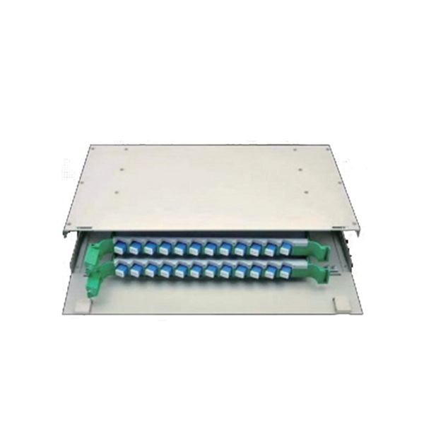
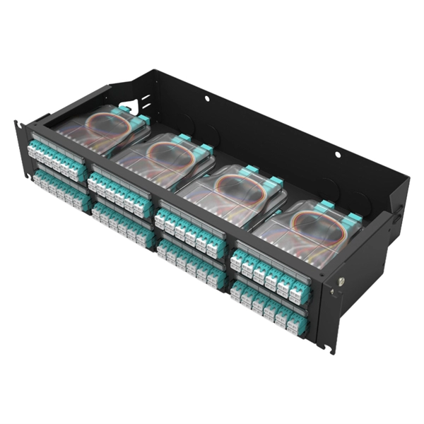
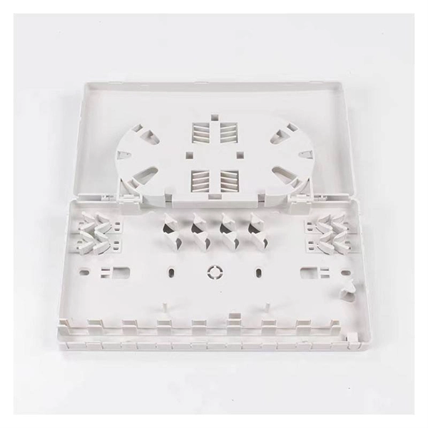
At its core, a fiber termination box combines hardware and software components to facilitate fiber optic connections. The hardware includes protective enclosures, splice trays, adapters, connectors, and patch panels. A Fiber Terminal Box (FTB) is a customer-side termination and distribution device used at the end of the optical network. It is small, so it is considered a mini version of the optical distribution frame or optical distribution frame (ODF). The number of ports of fiber optic junction boxes ranges from 8. A fiber optic junction box, also known as a fiber optic distribution box or termination box, is a protective enclosure that facilitates the connection and management of fiber optic cables. It serves as a central point for organizing and distributing optical fibers, ensuring efficient connectivity. Fiber termination boxes are essential components in modern telecommunications infrastructure. They serve as the critical junction points where fiber optic cables connect, splice, and distribute data signals efficiently and securely. Here's a structured breakdown. This article provides an in-depth comparison of fiber terminal boxes and junction boxes to help clarify their differences and deepen your understanding.
[PDF]

In this case use an optical power meter (OPM) and test the input port of the splitter for the optical power level (dBm) from the OLT at 1490 nm. If there is no or reduced power then the patchcord or OLT is the culprit. If the power level is reduced it could be as simple as a. So for this simple 1X2 splitter, how do we test it? Simply follow the same directions for a double-ended loss test. Attach a launch reference cable to the test source of the proper wavelength (some splitters are wavelength dependent), calibrate the output of the launch cable with the meter to set. Optical splitters in the outside plant (OSP) are used mostly in passive optical networks (PONs) for fiber-to-the-user (FTTx) networks, and are often overlooked as failure points. In this article I focus on a few basics of optical splitters, their applications, typical causes of failures, and how to. Now, we test the simplest 1x2 optical splitter as the picture shown below. 001 dB), OTDR (for reflection event detection). Cleaning tools. The CertiFiber® Pro Optical Loss Test Set (OLTS) can be used to check that the loss of a PON Splitter (often referred to in various standards as a non-wavelength-selective or wavelength-selective branching device) to check that it is within the allowed defined limits. The CertiFiber® Pro has an.
[PDF]

A typical fiber optic splice enclosure consists of several key components that work together to protect and organize the fiber splices. Standard enclosures contain: 1) Housing, 2) Cable fixation clamps, 3) Splice trays, 4) Sealing system. A splice box (also known as splice distributor) is a housing in which fiber optic cables begin or end. Fiber optics are fanned out in splice boxes that are situated at the end of fiber optic transmission paths. Optical cable joint box The optical cable joint box permanently connects two optical cables together and has a joint part for protecting components. The optical cable connection part, that is, the optical cable joint, is the part where the. An optical cable split fiber box, also known as a fiber distribution box or fiber optic splice closure, is a device used to terminate, splice, and distribute optical fibers. In this response, we will focus on the. This guide optimizes the original text by delving deeper into the three pillars of fiber network longevity: the impact of splicing technology, the strategic selection of splice boxes, and the essential maintenance protocols needed to ensure sustained, high-speed functionality. Fibre optic cables are manufactured in standardized lengths –.
[PDF]
Huawei offers a range of powerful aggregation switches designed to meet the diverse networking needs of modern enterprises. These switches serve as critical intermediaries between access and core layers, ensuring high-speed data transmission, intelligent traffic management, and. This document provides campus networks typical configuration examples and feature typical configuration examples. "Feature Typical Configuration Examples" provides. Hello, my name is Bob, and I am a Senior Engineer with the Technical Services team at network-switch. I am also a certified Cisco CCIE professional and HCIE certifed engineer, which reflects my expertise in networking and my dedication to delivering high-quality technical solutions. Specific requirements are as follows: The two active links have. MLAG is an advanced link aggregation technology that enables a device (such as a server or switch) to connect to two independent switches simultaneously. To the connected device, these two switches appear as a single logical system. If one switch or link fails, traffic automatically flows through. "Campus Networks Typical Configuration Examples" provides typical campus network networking modes and a variety of deployment examples. You can configure required features after.
[PDF]

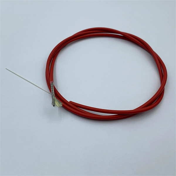
Multi-mode fiber optic patch cords utilize a larger core size, typically around 50-100 microns, allowing them to carry multiple modes of light. This design enables the transmission of data over relatively short distances with high bandwidth capabilities. A fiber-optic patch cord is a fiber-optic cable capped at each end with connectors that allow it to be rapidly and conveniently connected to telecommunication equipment. This is known as interconnect-style cabling. A fiber-optic patch cord is constructed from a core with a high refractive. These short fiber optic cords connect transceivers, switches, patch panels, and servers. Without them, even the best optical modules and switches cannot deliver performance. As data rates increase from 10G → 100G → 400G → 800G, patch cables must handle more bandwidth, more density, and stricter. Fiber optic patch cords, also known as fiber optic patch cables or fiber jumpers, are indispensable components in modern optical networks. They act as the critical link for interconnecting devices like optical switches, servers, and distribution frames. Understanding the various technical. Fiber patch cables, also called fiber-optic patch cords, are cables typically containing one or two optical fibers, which are equipped with standardized fiber connectors on both ends. The function of the fiber patch cord.
[PDF]

Sensitivity Test: Confirms that the protection works properly for internal defects in the protected zone. Inject primary current via one set of CTs, with one current flowing inward & the other outward. If the CTs are properly connected, there should be no operating current at the. A protective relay is basically an electrical device that detects a fault in a power system and initiates the operation of the circuit breaker to isolate the defective section or component from the rest of the system. In other words, the prime function of protective relays is the timely and. To conduct the tests effectively the following devices and equipment are required: Primary Injection Test Kit – for injecting large currents directly into CT circuits. Secondary Injection Test Kit – Simulates relay inputs with the controlled currents and voltages. It emphasizes selectivity, coordination, fault response, and system behavior rather than individual relay devices. This prevents damage to equipment, reduces downtime, and safeguards. This handbook covers the code of practice in protection circuitry including standard lead and device numbers, mode of connections at terminal strips, colour codes in multicore cables, dos and donts in execution. Its main purpose is to safeguard electrical equipment like transformers, generators, and transmission lines from damage due to.
[PDF]
This article will focus on the failure rates of optical modules, analyze the primary causes of failure in traditional Digital Signal Processing (DSP) modules, compare failure rates utilizing LPO technology, and discuss the advantages presented by LPO modules. Linear Pluggable Optics (LPO) are a new optical transceiver technology. The idea is simple: instead of a DSP (digital signal processor) inside the module – replacing it with transimpedance amplifier (TIA) and a driver chip with high linearity and EQ capability – LPO shifts signal processing into. Copyright 2023, Coherent. Next-generation 400G and 800G modules for data centers, AI clusters, and telecoms — validated in a European lab, ready to ship from Europe. What is Low-Power Optical Transceivers (LPO)? Linear Pluggable Optics (LPO) replace the DSP inside the optical module with linear analog components, shifting. QSFP-DD LPO TRANSCEIVER DESIGNED FOR PCIE® GEN 5. 0 over optical link, enabling scalable server disaggregation and efficient rack-to-rack interconnects ideal for AI/ML and. Led by Cisco Optics experts, this MSA quickly gained broad industry support due to its vision to create cost-effective solutions for high-density multi-terabit switching, routing, and transport networks. The goal was to define optical specifications that allow for future 100G and 400G pluggable.
[PDF]

Support Portal provides access to various services for Nokia Customers and Partners, such as Product Documentation, SW Downloads, Ticket Creation and Case Handling. The latest generation of Digital Coherent Optics (DCO) pluggable transceivers represents a breakthrough in the optical networking industry. By combining advances in silicon photonics and Digital Signal Processors (DSP) with Quad Small Form-factor Pluggable – Double Density (QSFP-DD) form factor. Ciena's WaveLogic 6 Extreme 1. 6T quantum-safe encryption solution on the Waveserver platform was designed with this in mind, supporting QKD system interworking and NIST-certified PQC algorithms. It delivers an always-on, wire-speed encryption solution, without impacting performance or adding. 400 Gigabit Ethernet (400G) transceivers are optical modules capable of handling data rates of 400 Gbps. With a transmission rate of up to 400 Gbps, 400G transceivers offer double the capacity of their predecessor (200G transceivers). 400G. ONU, or Optical Network Unit, is a networking device that connects your home or business to the internet using fiber optic cables. It's like a bridge between the vast internet world and your personal network. ONU is a small device that sits somewhere in your house. When you connect your computer. C-Data's ONU products include models that offer data, data + voice, data + CATV, and Triple Play services. They support TR-069 and provide excellent compatibility with third-party OLT systems.
[PDF]
Recommendation ITU-T L. 163 describes criteria for the installation of optical fibre cables defined in Recommendation ITU-T L. 110 in remote areas with lack of usual infrastructure for installation including the procedures of cable-route planning, cable selection, cable-installation. The Fiber Optic Association, Inc. (FOA) was founded in 1995 to help develop the workforce to build the fiber optic networks to support a rapid expansion in communications and the Internet. The charter of the FOA was to promote professionalism in fiber optics through education, certification, and. specifications under which the various work for trenching & laying of optical fiber cable are to be executed by the Vendor. The broad guidelines as laid down by TEC India, for laying of OFC networks are to be followed. Underground cables are pulled in conduit that is buried underground, usually 1-1. 2 meters (3-4 feet) deep to reduce the likelihood of accidentally being dug up. In extreme cold climates, cables may need to be buried at greater depths where there. If we can reduce failures and increase the service life of optical cables by carrying out communication optical cable construction in a standardized manner, it is worth understanding and learning for us telecommunications construction workers. To this end, overhead optical cable construction.
[PDF]

Towers are not rooted by only pouring concrete—they require extensive soil analysis, wind loads, types of towers, and seismic activity to determine the necessary foundation for safety and sustainable use. A communication tower foundation design is the structural blueprint that determines the anchor point of the tower on the ground. This article delves into the intricate process of civil construction tailored. Tower owners must comply with a multi-layered regulatory, engineering, and safety framework that governs tower siting, where a cell tower can be built, how it must be designed, and how it operates throughout its lifecycle. These requirements ensure public safety, structural integrity, regulatory. Here are six foundation types for communication towers that work for a wide range of situations and environments. If you're planning a new installation, knowing the basics of these foundations can help you establish a secure and durable tower that will be a community asset for years to come. Telecom (Telecommunications) towers are a generic description of radio masts and towers built primarily to hold telecommunications antennas. As such antennas often have a large area and must be precisely pointed out, such towers have to be designed and built to limit wind induced movement. The Contractor shall employ a quality control program that will ensure that engineering, fabrication.
[PDF]
In this guide, we'll break down everything you need to know to install a distribution box correctly and confidently. Choose the right box based on environment (indoor/outdoor), load capacity, and durability. Check for proper IP/NEMA ratings and material quality. A distribution box is the heart of any electrical system. It takes the incoming power and safely distributes it to different circuits throughout your building. Whether in a home or an industrial facility, this box keeps your electrical setup organized, functional, and efficient. However, the key to. In modern electrical systems, cable distribution boxes (also known as electrical distribution boxes or distribution boxes) play a crucial role as the key hub for managing, distributing, and protecting circuits. Just like travelers need clear pathways and safety protocols, your electrical circuits need proper management to prevent chaos. This article details the process of installing them, which helps you comprehend distribution boxes. Learn how to wire a distribution box step by step! This video shows real on-site footage of electrical installation, demonstrating safe and standardized wiring methods used by professionals. Site selection requirements: The distribution box should be installed in an area close to the power supply to reduce.
[PDF]
Global Fiber Optic Sensors Market Research Report By Type (Intrinsic, Extrinsic), By Component (Receiver, Transmitter, Fiber Optic Cable, Optical Amplifier), By End-User (Transportation, Medical, Defense, Industrial, Oil and Gas), By Region (North America, Europe, Asia. Global Fiber Optic Sensors Market Research Report By Type (Intrinsic, Extrinsic), By Component (Receiver, Transmitter, Fiber Optic Cable, Optical Amplifier), By End-User (Transportation, Medical, Defense, Industrial, Oil and Gas), By Region (North America, Europe, Asia. The global Distributed Fiber Optic Sensor Market was valued at USD 1,411. 7 million in 2024 and is projected to grow from USD 1,581. 9% during the forecast period. The market is driven by rapid digitalization and automation within the. The global distributed fiber optic sensor market size was valued at USD 1. 9% from 2026 to 2033.
[PDF]