5mm (SC/ST/FC/E2000) versions, this pen is a must-have maintenance tool for engineers in fiber optic networks, ensuring stable performance and low insertion loss. Price and other details may vary based on product size and color. 25mm LC Fiber Cleaner Pen. LCUPC Optical Connector Cleaner & Endface Cleaning Pen Comes with Damage Protection Case & Dust Caps Need help?. The HTO9-CPM250 Mini Fiber Optic Cleaner Pen is a compact, high-precision tool designed to clean contamination from fiber connector end-faces. With an ergonomic push-action design, it efficiently removes dust, oil, and debris from both adapter ports and connector plugs without using alcohol or. This is a 1. 25mm One-Click Fiber Optic Cleaning Pen that is great for quickly removing dirt, dust, oil, and grease from optical fiber adapters. It is designed to clean LC and MU connectors. This fiber optic cleaning pen is great at cleaning hard-to-reach areas, ferrule end-faces and inside the plug. The Best applications for this cleaner are Fiber network panels and assemblies, Outdoor FTTX applications, Cable assembly production facility, Testing laboratories Server, switches, routers, and OADMS with SC, ST, and FC interface. SC Fiber Optic Cleaner Pen is designed to specially work well with. Despite its light weight and compact size, the fiber optic cleaning pen can clean over 1000 connector end surfaces with just one unit. Designed for SC, FC, ST (2. High-Performance Cleaning.
[PDF]
A cable tray is a structural system used to support insulated electrical cables used for power distribution, communication, and control. It provides a secure pathway that prevents cable damage, simplifies maintenance, and reduces the risk of overheating. Explore various cable tray types and sizes for electrical installations. Learn about ladder, perforated, solid-bottom, wire mesh, and channel trays in this complete guide. What is Cable Tray Systems? 1. Wire Mesh Cable Tray. When it comes to modern wiring systems, cable trays play an essential role in managing, protecting, and organizing cables. Whether you are setting up electrical wiring in an office, industrial plant, or even under a desk, choosing the right cable tray ensures safety, efficiency, and neatness. Unlike conduit systems, cable trays allow cables to be laid in bundles, improving accessibility, heat. Cable tray are essential components in electrical and telecommunications installations, providing a practical solution for cable tray management in both commercial and industrial environments. They are designed to accommodate and support multiple cables, providing a systematic approach to wiring.
[PDF]

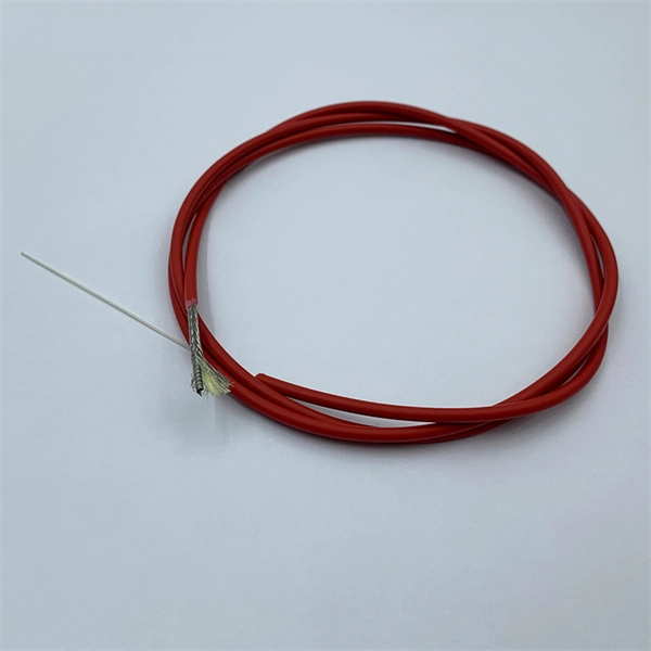
How to hardwire a Self-Regulating heat cable into a junction box, with a tutorial of the final end seal. First thing, get the sealing ring and connect it onto the connector body. Make sure it gets onto the very e. Safety comes first, and clear info makes it doable. Know Your. We'll show you how to size the heater, run a new, safe 240-volt circuit and install a programmable thermostat. Most homes have sufficient capacity for the new circuit in the service. If you're working with heating cables, understanding how to connect them safely and efficiently is crucial. In this guide, we'll break down the steps in simple terms. Whether you're a DIY enthusiast or a professional, this article is here to help. Stay safe and ensure proper installation with these. I need help wiring an electric furnace with heat elements. I ran number 6 wire with ground from my 100 amp service box where I installed a 60amp double pole breaker. The furnace comes with an other set of breakers one 60amp and one. A distribution board or distribution box is where the main power supply is distributed to multiple loads. Single Phase Distribution Box generally consists of Double Pole MCBs, Single Pole MCBs, and RCCBs.
[PDF]
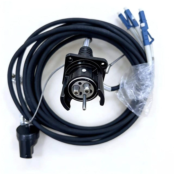
This is the latest revision of this Recommendation that was first created in 1988. Recommendation ITU-T G. 654 describes the geometrical, mechanical and transmission attributes of a single-mode optical fibre and cable which has the zero-dispersion wavelength around 1300 nm wavelength, and which is loss-minimized and cut-off wavelength shifted at around the 1550 nm wavelength. The superior attributes of TXF ® optical fiber, compliant to ITU-T G. E, allow for the provision of an additional network margin that can be leveraged to enable reliable, high-data-rate transmissions over longer spans and extended reach. This allows long-haul networks with TXF fiber to be. ACOME and Sumitomo Electric have developed a new hybrid solution that allows network operators to deploy a single universal cable that supports both current and future network needs. Upgrading to 800G and above requires fewer repeaters to amplify the optical signals and can also avoid the need for. Recommendation ITU-T G.
[PDF]
This article will focus on the failure rates of optical modules, analyze the primary causes of failure in traditional Digital Signal Processing (DSP) modules, compare failure rates utilizing LPO technology, and discuss the advantages presented by LPO modules. Linear Pluggable Optics (LPO) are a new optical transceiver technology. The idea is simple: instead of a DSP (digital signal processor) inside the module – replacing it with transimpedance amplifier (TIA) and a driver chip with high linearity and EQ capability – LPO shifts signal processing into. Copyright 2023, Coherent. Next-generation 400G and 800G modules for data centers, AI clusters, and telecoms — validated in a European lab, ready to ship from Europe. What is Low-Power Optical Transceivers (LPO)? Linear Pluggable Optics (LPO) replace the DSP inside the optical module with linear analog components, shifting. QSFP-DD LPO TRANSCEIVER DESIGNED FOR PCIE® GEN 5. 0 over optical link, enabling scalable server disaggregation and efficient rack-to-rack interconnects ideal for AI/ML and. Led by Cisco Optics experts, this MSA quickly gained broad industry support due to its vision to create cost-effective solutions for high-density multi-terabit switching, routing, and transport networks. The goal was to define optical specifications that allow for future 100G and 400G pluggable.
[PDF]
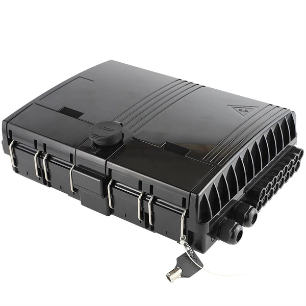
Recommendation ITU-T L. 163 describes criteria for the installation of optical fibre cables defined in Recommendation ITU-T L. 110 in remote areas with lack of usual infrastructure for installation including the procedures of cable-route planning, cable selection, cable-installation. The Fiber Optic Association, Inc. (FOA) was founded in 1995 to help develop the workforce to build the fiber optic networks to support a rapid expansion in communications and the Internet. The charter of the FOA was to promote professionalism in fiber optics through education, certification, and. specifications under which the various work for trenching & laying of optical fiber cable are to be executed by the Vendor. The broad guidelines as laid down by TEC India, for laying of OFC networks are to be followed. Underground cables are pulled in conduit that is buried underground, usually 1-1. 2 meters (3-4 feet) deep to reduce the likelihood of accidentally being dug up. In extreme cold climates, cables may need to be buried at greater depths where there. If we can reduce failures and increase the service life of optical cables by carrying out communication optical cable construction in a standardized manner, it is worth understanding and learning for us telecommunications construction workers. To this end, overhead optical cable construction.
[PDF]
There are several diagnostic methods to help troubleshoot fiber optic connectors, and the diagnostic method is to cross-section the fiber optic connector. This technology allows us to actually look inside the fiber optic connector to see defects and pinpoint the cause of. Fiber design and transmission technology have collaboratively evolved to increase bandwidth. Dig-ups dominate! Cablers have very little influence on the majority of causes of cable field failures. While a small percentage, we can examine the “intrinsic” cable failures and what is done to prevent. Connector failure is most frequently the result of a dirty or damaged end-face. Fiber-optic connector: SC type In the connector, the element that holds the fiber and provides the alignment positioning is the ferrule. The. In August of 1999, Boeing Corporation (Boeing) engineers being used on International Space Station flight a defect in the glass fiber (see Figure 1, “Rocket and NASA engineers and managers, Boeing created and reliability of the cable installed in the U. Fiber coupling can be accomplished by fusion splicing.
[PDF]
Market Size by Fiber Type, by Deployment, by Cable Type, by End Use Industry – Global Forecast. The global fiber optic cable market was valued at USD 13 billion in 2024 and is estimated to grow at a CAGR of 10. The Fiber Optic Cable Market Report is Segmented by Cable Type (Armored Cable, Non-Armored Cable, and More), Fiber Mode (Single-Mode Fiber, Multi-Mode Fiber, and More), Installation Type (Aerial/Overhead, Underground/Buried, and More), End-User Industry (Telecommunication, Power Utilities and Smart. The global Fiber Optic Cable Market is anticipated to be worth USD 5. It is expected to grow steadily and reach USD 11. This growth represents a CAGR of 7. 21% during the forecast period from 2026 to 2035. I need the full data tables, segment breakdown, and. The fiber optics industry is projected to reach USD 6. 8 billion by 2029 from USD 3. Rapid expansion of data centers, cloud services, and 5G infrastructure is driving strong adoption of fiber optic solutions. 64% between 2023 and 2028. The market is experiencing significant growth, driven by the increasing demand for high-speed internet connectivity and the expansion of data centers.
[PDF]

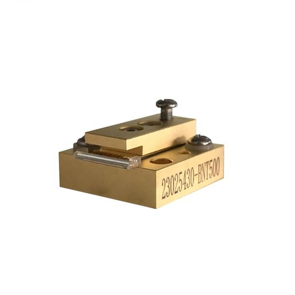
An optical module's actual transmit power measured by an optical power meter is lower than the nominal transmit power of the power module. The possible causes are: Bores of the optical module are contaminated. Stable optical power is the foundation of every high-capacity optical transport system. Even minor deviations—whether too high, too low, or unstable—can impact signal integrity, trigger service alarms, or interrupt traffic on DWDM, OTN, or long-haul optical line systems. This is the domain of Cell-to-Module (CTM) power loss, a series of. This paper reviews methods for reducing different optical and electrical loss mechanisms in PV modules and for increasing the optical gains in order to achieve higher CTM ratios. Various solutions for optimizing PV modules by means of simulations and experimental prototypes are recommended. Have you ever experienced an unexpected network outage due to the failure of an SFP/SFP+ optical transceiver? Network outages can bring your ability to communicate and work to a halt, and your IT team will likely be frantically looking for a solution. It is important to understand how to. This article provides an in-depth analysis of two key performance indicators of optical modules: transmitter power and receiver sensitivity. Transmitter power characterizes the average optical power output from the laser under rated conditions, while receiver sensitivity indicates the minimum.
[PDF]