With robust design, reliability, scalability, security, performance, interoperability and compatibility, network switches enable organizations to overcome the challenges of modern industrial environments and unlock new levels of performance, resilience and innovation. These ruggedized network switches play a key role in providing reliable and secure communications in a variety of industrial environments. Let's take a look at the advantages that make industrial switches essential in today's connected automation world. Industrial environments are notorious for. Essentials for the fast-changing world of industrial automation and smart infrastructure today include having reliable, efficient network connectivity. The pivotal part of these robust systems is the industrial network switch, which guarantees smooth communication between various devices, sensors. In the rapidly advancing industrial landscape, the importance of an industrial network switch cannot be overstated. As industries evolve, so too do the features that define the best switches. Industrial-grade Ethernet switches solve such issues in order for seamless communication to occur in the various industrial sectors. Common technologies and protocols used in ICS plant floor networking include:Ethernet/IP, PROFINET, Modbus TCP/IP, DeviceNet, CIP (Common Industrial Protocol), and PTP. The industrial network switch plays a crucial role in modern industrial communication. 74 billion in 2021 to $2.
[PDF]

This category brings together switch options commonly used in industrial control architecture, where durability, operator visibility, and compatibility with the wider system matter as much as the switching function itself. TRENDnet's 10-Port Hardened Industrial Gigabit DIN-Rail Switch, model TI-G102, has eight dedicated gigabit ports, plus two gigabit RJ-45 / SFP shared ports. Users are able to connect eight devices to the switch, while still providing two gigabit ports for additional network connections. The switch. With pride, we have served over 50 clients across Myanmar, providing a comprehensive range of top-quality automation services. From advanced Control Engineering to seamless IoT Integration, our solutions are designed to meet the diverse needs of our clients. We don't just offer cutting-edge. In industrial panels, process equipment, and automation systems, control switches help translate human commands into clear electrical actions while supporting safe, repeatable workflows. We provide a wide business field and development services. H7-BM1 30 (B), University Avenue, Yangon, Myanmar. Like us on Facebook!. Cosmic Power is the best electrical engineering company and electrical panel builder in Yangon, Myanmar. We do switchgear panels manufacturing and installation in Burma. We produce low and medium voltage control and switchgear panels with after sales services and guarantee within warranty period.
[PDF]
Also, please take a look at the list of 19 industrial ethernet switch manufacturers and their company rankings. Omnitron Systems Technology, Inc. ANTAIRA TECHNOLOGIES, LLC. Here are the top-ranked industrial ethernet switch companies as of May. A network switch (or Ethernet switch) is a communication device that is used to distribute data over cable networks. It usually comes in the form of a box with several Ethernet or fiber optic ports. The company continues to lead through heavy investment in research and development, focusing on IoT. From high-performance ethernet switches to more cost-effective options, the right choice depends on your needs. Meter delivers fully managed network switches, so you get enterprise-grade performance without the issues. What you'll get from our article: A good network switch does more than shuffle. Manufacturer of standard and custom foot switches for medical, adhesive dispenser, and abrasive blaster applications. Features vary depending upon model, including handles, toe loops, wired, wireless, and anti skid foot or base pads. Also, suitable for adhesive dispensers, abrasive blasters. Ruijie offers next-generation industrial Ethernet switches designed for harsh industrial environments, providing flexible full-gigabit access as well as 10GE uplink ports, and supporting a wide operating temperature range and surge protection. Subscribe to our newsletter for the latest ICT trends.
[PDF]
An optocoupler is a coupling device used to couple optical signals. It's primarily employed to combine and split signals in optical networks, and it's also referred to as a directional coupler. Image alt: Optocoupler-Optical coupler The figure above depicts a 2x2 coupler with two input ports and. It is widely used for coupling or splitting light waves through waveguides or fibers and can be availed in the form of either active or passive devices. The main difference between active and passive couplers is that the passive coupler redistributes the optical signal without converting optical. Optical couplers, essential components in the realm of fiber optics and telecommunications, stand at the forefront of enabling efficient, versatile, and reliable optical signal processing. In ophthalmic imaging; the coupler: A-Z > O > What Is an Optical Coupler? Share Provide a valuable. A coupler is an optical device that combines or splits optical signals. The basic principle of a coupler is to transfer optical power from one or more input ports to one or more output ports.
[PDF]
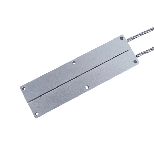
Fiber optic pressure sensors operate based on the principle of light modulation in optical fibers. When pressure is applied to the sensing element, it changes the properties of the fiber, such as the refractive index or the intensity of the light. These sensors are gaining popularity. Fiber-optic sensing (FOS) technology has emerged as a cutting-edge research focus in the sensor field due to its miniaturized structure, high sensitivity, and remarkable electromagnetic interference immunity. Compared with conventional sensing technologies, FOS demonstrates superior capabilities in. This article explains the structure, working principle, advantages, and disadvantages of Fiber Optic Pressure Sensors. Compared to traditional electronic pressure sensors, they offer advantages such as immunity to. Fiber optic pressure sensors are transforming how industries monitor and manage critical systems. Unlike traditional sensors, these devices use light to measure pressure changes, offering high accuracy, immunity to electromagnetic interference, and durability in harsh environments.
[PDF]
The AWGs are used to multiplex channels of several wavelengths onto a single optical fiber at the transmission end and are also used as demultiplexers to retrieve individual channels of different wavelengths at the receiving end of an optical communication network. Arrayed waveguide gratings (AWG) are commonly used as optical (de)multiplexers in wavelength division multiplexed (WDM) systems. These design of these devices are based on an. A 32-channel 50-GHz spaced arrayed-waveguide grating with our innovative configuration has been designed and fabricated. The performance of the device has been fully tested by using a tunable laser light source, optical power meter, and polarization controller. AWG has filtering characteristics and versatility, which can obtain a large number of wavelengths and channels, to realize the multiplexing and demultiplexing. The arrayed waveguide grating (AWG) is a planar versatile light-dispersion component with high accuracy, robustness, and design flexibility. It has become an attractive component not only for telecommunication (e., multiplexer or demulti-plexer)[2,3] but also for medical imaging,[4–6]. uide Grating Routers (WGRs). The acronym AWG, introduced by Takahashi , is the most frequently used name today and wi l also be used in this text. Together with Thin-Film Filters and Fibre Bragg Gratings, AWGs are the most important filter type applied in WDM networks, and with the advance of.
[PDF]
Essentially, an OXC is a device that allows for the interconnection of multiple optical fibers, facilitating the routing of optical signals from any input fiber to any output fiber. This functionality is crucial for managing the vast amounts of data transmitted through optical. An optical cross-connect (OXC) is a network device that switches high‐speed optical signals between fiber inputs and outputs without converting them to electronics. In the 1980s, when transmission speeds supported by optical fibers increased from 45 Mbit/s to 2. 5 Gbit/s, carrier networks. The Optical Transport Network has emerged as a dominant standard to address these needs, offering robust transmission, multiplexing, switching, and management capabilities for optical signals. Compared with traditional ROADM based on separate boards and inter-board fiber patch cords, OXC uses integrated interconnections to build an all-optical switching resource pool, achieving highly integrated, fiber. Optical Cross-Connects (OXCs) are critical components in modern optical networks, enabling the switching of optical signals between different paths without the need for electrical conversion. This technology supports scalability, flexibility, and high performance for backbone networks, data‑center interconnects, and next-generation mobile.
[PDF]

Numerical relay are embedded with specialized digital signal processor (DSP) as the computational hardware. By using DSP as the relay's processor, the relay is capable of meeting the fundamental protective requirements such as reliability, sensitivity, selectivity and speed . Thus, various protective devices are used to protect the power system, of which digital signal processor (DSP) numerical relays are capable of significantly improve protection operations. Therefore. Manuals and User Guides for Samwha DSP DSP-VIP-PM Motor Protection. We have 1 Samwha DSP DSP-VIP-PM Motor Protection manual available for free PDF download: Manual Samwha dsp DSP-VIP-PM Motor Protection Pdf User Manuals. View online or download Samwha dsp DSP-VIP-PM Motor Protection Manual. Many of the new protection relays are microprocessor based and are generally referred to as numerical relays. This means that signals from transducers are sampled at fixed time intervals, digitally encoded, and processed by equipment which resembles a computer to derive relaying information, e.
[PDF]
Segmented dimming is a feature of the Magic Leap 2 that applies a darkening tint behind specific digital content. Similar to a drop-shadow, this dimming improves the visual quality of a digital object by making it appear brighter or more opaque. The dimmer uses a lower resolution panel and therefore, developers must be conscious of it's use and is best used for larger objects. As of the February 2023 release, all virtual. The main scene of this project displays two cubes, one cyan and one red. The Segmented Dimmer material opacity will adjust based on the MLCamera stream value calculations. Think of this as a tint applied to the background under all the virtual content, in which you can control its opacity value. A Segmented Dimmer, which allows applications to locally. Th is function is commonly referred to as dimming control. Th is article describes some basic LED theory and several techniques used to provide dimming control to switched-mode LED drivers. Th e concept of the brightness of visible light from an LED is fairly easy to understand. Assigning a. It the utility model is related to LED light source room lighting field, more particularly to a kind of segmented LED dimming control circuit, a kind of segmented LED dimming control circuit, the light-source brightness of LED lamp is automatically adjusted to realize by the collective effect of.
[PDF]

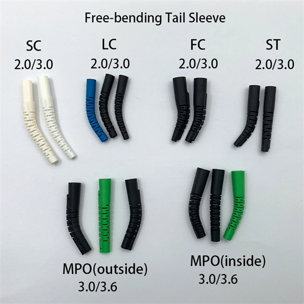
Protect fiber optic cable connections:The joint box provides physical protection for the fiber optic cable connection parts to prevent damage to the fiber optic cable caused by external environmental factors such as moisture, dust, chemical corrosion and mechanical damage. Provide a stable. Fiber optic sleeves are protective devices used for fiber optic connections. Splice protection sleeve, usually made of plastic or metal, are used to secure and protect the fusion joint between two optical fibers. Fiber Cable Joint Box is attributed to the mechanical pressure sealing joint system. Fiber Cable Joint Box is a continuous protection device for supplying optical, sealing and mechanical strength continuity between adjacent optical. The optical fiber terminal box is the terminal joint of an optical cable, one end of which is an optical cable, and the other end is a pigtail, which is equivalent to a device that splits an optical cable into a single optical fiber. The user optical cable terminal box installed on the wall, its. Fiber Optic Splice Closure is designed to protect optical fibers from debris, dirt, dust, moisture and water. As much of the fiber system is outside in a harsh environment, these fiber optic splice closures are designed to meet the tough protection requirements of fiber-optic splices. UnitekFiber. Overview Application of Optical Fiber Splice Closure/Joint Box/Joint Closure: 1. CATV environment.
[PDF]

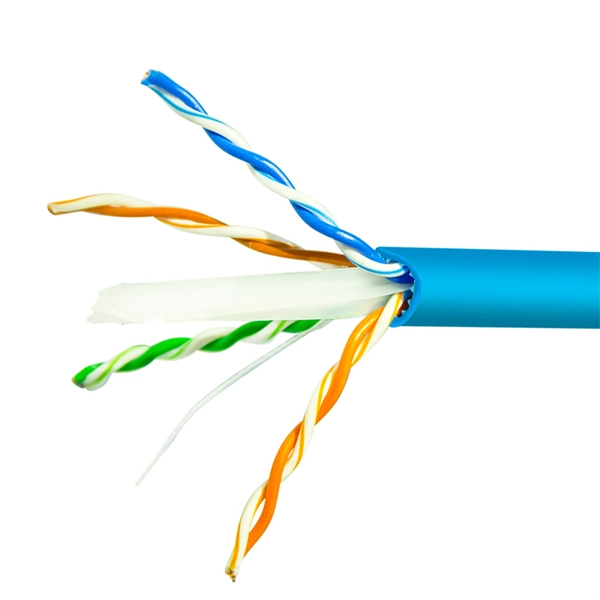
Multimode Fiber Optic Receivers are devices designed to interpret information contained in optical signals transmitted through multimode fibers. These receivers convert the optical signals into electrical signals, allowing the data to be processed and utilized by electronic systems. Multimode Fiber. They convert electrical signals into optical signals for transmission over fiber-optic cables and reverse the process at the receiving end. Now, the term 'multimode' stems from the fact that these transceivers use multimode fiber (MMF) cables, which can carry multiple beams of light — or 'modes' —. Multi-mode optical fiber is a type of optical fiber mostly used for communication over short distances, such as within a building or on a campus. Multi-mode links can be used for data rates up to 800 Gbit/s. Most systems operate by transmitting in one direction on one fiber and in the reverse direction on another fiber for full duplex operation. For applications where long-haul transmission is unnecessary, multimode SFP modules offer a practical. They have a wider core (around 50 to 62. 5 micrometers), which enables multiple modes or light paths to coexist within the fiber, thus resulting in modal dispersion at shorter distances but reducing its efficacy over longer stretches. The choice between Single-Mode Fiber (SMF) and Multimode Fiber.
[PDF]

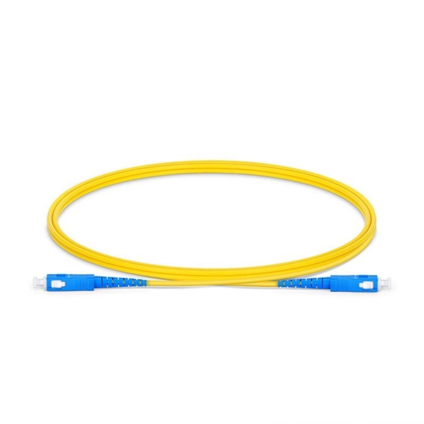
A PLC Splitter takes one optical signal and splits it into many outputs. This helps share signals in fiber optic networks. Pick the split ratio that matches what you need. Lower ratios work for fewer users. Choose the connector type like SC . PLC optical splitters (planar waveguide optical splitter) is a key component in optical fiber communication networks and is widely used in optical fiber distribution systems such as FTTH (fiber to the home) and PON (passive optical network). A fiber optic PLC splitter distributes a single optical signal into multiple outputs with high uniformity and low loss, making it ideal for. PLC splitter, also called Planar Waveguide Circuit splitter, is a device used to divide one or two light beams into multiple light beams uniformly or combine multiple light beams to one or two light beams. It is a passive optical device with many input and output terminals, especially applicable to. What Is a PLC Fiber Splitter? A PLC (Planar Lightwave Circuit) splitter is a passive optical device that evenly distributes optical signals into multiple output ports using silica waveguide technology. Choose the connector type like SC, LC, or FC. This. That's where PLC splitters come in. These compact passive components help service providers and network engineers distribute a single optical signal across multiple outputs without the need for power or complex configurations. If you're building or upgrading a fiber network and wondering what a PLC.
[PDF]

Cold aisle containment (CAC) is a proven data center cooling strategy that creates physical barriers around cold air supply zones, preventing contamination from hot exhaust air and eliminating the energy-wasting effects of air mixing. This approach transforms traditional hot aisle/cold aisle. Cold Aisle Containment isolates the cooled supply air from the cooling units within direct proximity of the air intake of critical equipment. An enormous amount of energy is used every day to maintain an acceptable intake temperature to the IT equipment. By isolating the cold aisle, containment reduces unintended mixing of cold supply air with hot exhaust air, maintaining uniform, predictable. The cold aisle layout is the most common starting point in data center design. Server racks are arranged in rows so that the fronts of the racks face each other, forming a corridor known as the cold aisle. A look at the science behind hot and cold containment aisles reveals that server racks stand in rows and alternate the way they face. One row faces forward so the server.
[PDF]
A distribution box serves as a central point for managing and distributing fiber optic cables. This device ensures reliable and efficient connectivity between various network components. By combining factory-installed connectors with spliced bare fiber, pigtails ensure that network installers can create fast, reliable, and cost-effective terminations. Without pigtails. A fiber pigtail is a type of fiber optic cable with a factory pre-terminated connector on one end and exposed fiber on the other. This design makes the fiber pigtail suitable for field termination using a mechanical or fusion splicer, playing a crucial role in the fiber optic cable installation. A Fiber Optic Termination Box is a small enclosure located at the terminal end of the fiber where it enters your customer premises. Its function is primarily to splice, secure, and protect the optical fibers connecting the incoming drop cable to the pigtail or patch cable. The connector end plugs into devices like transceivers or patch panels, while the bare end is typically fusion spliced to a fiber optic cable. You can splice the bare end with a fiber core of an optical cable, thus providing a connection for the fiber.
[PDF]
This guide provides instruction on how to install and configure your MS130R series switch. For more switch installation guides, refer to the switch installation guides section on. This guide provides step-by-step instructions for installing two common types of industrial switches: rack-mount, and DIN-rail switches. Choose the Installation Location: Select an appropriate spot on the DIN rail for mounting. This chapter describes how to start your switch and how to interpret the power-on self-test (POST) that ensures proper operation. No prior experience needed—just follow along and you'll have your switch installed and running in minutes. more In this video you'll see a complete, step-by-step guide to mounting. This typeface indicates command syntax, or represents information as it is displayed on the screen. When you see the word enter in this guide, you must type something, and then press the Return or Enter key. Do not press the Return or Enter key when an instruction simply says type. Here, we explore the four most common installation methods for industrial switches: Desktop installation is the most straightforward approach— placing the switch like a small box directly on a table, control panel surface, or equipment rack without extra fixtures. Simple setup: No tools required.
[PDF]