
Fusion Splicer Settings – Must-Know for Fiber Technicians! 🔧 At D-TECH TRADING, we're demonstrating the essential Fusion Splicer settings that every fi. more. Auto Mode is the most intuitive and user-friendly splice mode. The fusion splicer automatically detects the fiber type, such as single-mode (SM), multimode (MM), or dispersion-shifted (DS) fibers, and adjusts parameters like arc power and heating time accordingly. Applications: Ideal for beginners. Page 1 Fusion Splicer 19R+/70R+ Quick Reference Guide Splice Operation • When splicing only standard SM fibers (ITU-T G. 652), “SM AUTO” mode is recommended. It also outlines instructions for keypad usage. st Instruction manual Fusion Splicer Please read this instruction manual carefully before operating the equipment. Adhere to all safety instructions and warnings contained in this manual. Keep this manual in a safe place. There is a change without a previous notice. We are not responsible for the. Fusion splicing is the bedrock of high-performance fiber optic networks, enabling seamless signal transmission through permanent, low-loss fiber joins. As a leading provider of fiber optic infrastructure, Weunion leverages cutting-edge tools like the AI9 and AI10 fusion splicers, paired with.
[PDF]

This is where a small but mighty hero comes into play: the Mode Conditioning Patch Cable (MCP). In this guide, we'll demystify what a mode conditioning patch cable is, why it's essential in specific network scenarios, and how it can save you from a world of connectivity headaches. This guide offers the key technical insights you need to select and install the optimal fiber optic cabling solutions for your specific needs. Covers the basics of fiber optic technology, including how light waves transmit data through thin strands of glass or plastic, and why fiber optics surpass. Fiber optic cables use light to transmit data, whereas traditional cables rely on electrical signals, which are more prone to interference and loss over distance. Connector types play a crucial. Fiber optic technology has transformed the way we transmit data, enabling faster, more reliable connections than traditional copper cables. Understanding fiber optic cable types is essential for anyone looking to build or maintain efficient fiber networks. We'll also. This is a plain-English guide for facilities and IT teams who want fiber that performs well, stays organized, and doesn't turn every add/change into a disruption. Start with the link's distance and speed, then pick single-mode (OS) or multimode (OM)—not the other way around.
[PDF]

A Mode Conditioning Patch Cord (MCPC) is a specialized fiber patch cord designed to control the launch condition of light from a single-mode transmitter into a multimode fiber. Fiber optic cables primarily come in two types: Multimode Fiber (MMF): Has a larger core, allowing multiple light modes (paths) to travel. It's designed for short-distance, high-bandwidth applications within buildings or campuses. Common types are OM1, OM2, OM3, and OM4. Its primary purpose is to reduce differential mode delay (DMD) and prevent bandwidth limitation when legacy multimode. FS offers OM1 & OM2 mode conditioning fiber optic patch cables (MCP) in any connector & cable length, optimal for eliminating differential mode delay effects. This document describes the installation and use of the mode-conditioning patch cords listed in Table 1. 3z-compliant optical fiber assembly consisting of a single-mode fiber permanently coupled off-center to a 62. 5/125) fiber optic cable by offsetting the Singlemode Laser launch from the.
[PDF]

Learn how to safely wire a single-pole (one way) light switch in this beginner-friendly tutorial. Whether you're replacing an old switch or doing your first DIY electrical project, this guide will walk you through every step — no experience needed!. more. This page contains wiring diagrams for household light switches and includes: a switch loop, single-pole switches, light dimmer, and a few choices for wiring an outlet/switch combo device. That's because virtually all light switches that control 120-volt fixtures are single-pole switches. Most light switches are also single-throw, which. Summary: Fully explained wiring diagrams and photos show how to wire switches including: single switches, 3-way switches, 4-way switches, and dimmer switches. and Be Sure to Subscribe! Make sure the circuit power has been turned off, and mark the circuit breaker or fuse to indicate that work is. A distribution board or distribution box is where the main power supply is distributed to multiple loads. And all the switching and protective devices are installed in the distribution box. Single Phase Distribution Box generally consists of Double Pole MCBs, Single Pole MCBs, and RCCBs. Wiring a single light switch may seem like a daunting task, but with the right tools, a bit of patience, and this comprehensive guide, you'll be able to tackle this DIY project with confidence. Remember, while this guide provides detailed instructions, always prioritize safety and consult a.
[PDF]
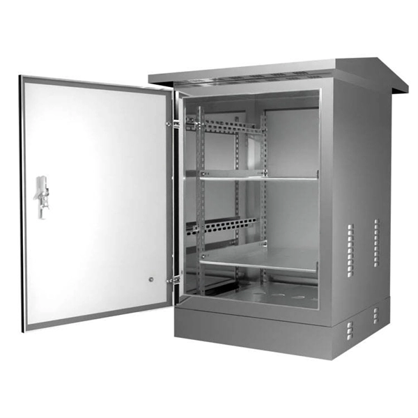
It integrates fiber splicing, splitting, distribution, storage, and cable connection into one unit, providing solid protection and efficient management for building reliable FTTX networks. Total Enclosed Structure: Ensures maximum protection. This fiber optic distribution box serves as a termination point for feeder cables to connect with drop cables in FTTX communication network systems. It is. An optical distribution frame (ODF) is a frame used to provide cable interconnections between communication facilities, which can integrate fiber splicing, fiber termination, fiber optic adapters & connectors and cable connections together in a single unit. It can also work as a protective device. A Fiber Optic Termination Box is a small enclosure located at the terminal end of the fiber where it enters your customer premises. Its function is primarily to splice, secure, and protect the optical fibers connecting the incoming drop cable to the pigtail or patch cable. We separate these products into multiple groups based on application to meet your specifications for mount location and termination capacity.
[PDF]

Not all splitters are created equal. Here are the main types you'll encounter: The "1×N" notation indicates one input fiber and N output fibers. A 1×2 splitter divides the signal into two outputs, while a 1×8 splitter divides it into eight. The more splits, the. By dividing a single optical signal from a central Optical Line Terminal (OLT) into multiple outputs for Optical Network Terminals (ONTs) at users' homes, splitters eliminate the need for dedicated fibers to each residence—slashing infrastructure costs while scaling network reach. This guide. A fiber-optic splitter, also known as a beam splitter, is based on a quartz substrate of an integrated waveguide optical power distribution device, similar to a coaxial cable transmission system. The optical network system uses an optical signal coupled to the branch distribution. The fiber optic. Optical couplers can split or join signals in fibers. You can connect many users to one port with 1:n or 2:n splitters. These devices work both ways, which helps strong network communication. In a Passive Optical Network (PON), a single optical fiber carries massive amounts of data using light. They are named by the number of inputs and outputs, so a splitter with one input and 2 outputs is a 1X2, and a PON splitter with one input and 32 outputs is a 1X32.
[PDF]
Rodent damage in underground or aerial installations. Symptoms: Gradual performance decline over months/years. UV exposure degrading jacket materials. Use Case: Identifying macrobends, breaks, or sharp bends in. In the high-stakes world of optical networking, even a minor disruption in a Pigtail Fiber connection can cascade into costly downtime, affecting data centers, telecom services, or industrial systems. This article equips engineers and network operators with actionable strategies to diagnose. Fiber pigtail failures can lead to unexpected signal loss, link instability, and repeated maintenance. Understanding how to identify early warning signs can help reduce downtime and protect your network from unnecessary failures. A visual check is often the first step when diagnosing a defective. However, when signal loss occurs in a 12 fiber pigtail, it can lead to disruptions in network performance, such as decreased data transfer speeds, increased error rates, or even complete outages. Understanding the potential causes of signal loss and implementing effective troubleshooting methods is. Executive Summary: A fiber optic pigtail is one of the most commonly specified yet least understood components in structured cabling. Dust or oil contamination leads to signal loss. Always clean fibers before splicing. Using the wrong connector (LC vs SC) can cause compatibility.
[PDF]

However, essentially, optical fiber patch cords are more like "finished connection lines", while optical fiber pigtails are "semi-finished connectors". The difference in this core positioning determines the vast disparity between them in structure, connection methods. Executive Summary: A fiber optic pigtail is one of the most commonly specified yet least understood components in structured cabling. Get the wrong connector type, the wrong polish, or skip proper fusion splicing technique—and you're looking at elevated signal loss, increased back reflection, and a. When you build or upgrade a fiber network, the same four words pop up everywhere— fiber optic (bare fiber), pigtail, patch cord, optical cable. They're related, but they are not interchangeable. Mixing them up drives costs higher, increases loss, and slows your rollout. The good news? Once you nail. A fiber pigtail is typically a fiber optic cable with one end factory pre-terminated fiber connector and the other exposed fiber. It is usually suitable for field termination using a mechanical or fusion splicer. The connector end plugs into devices like transceivers or patch panels, while the bare end is typically fusion spliced to a fiber optic cable. This setup ensures. As outlined in T13: Fiber Optic Fundamentals, an optical fiber is a coaxial cylindrical dielectric waveguide with a core refractive index exceeding that of its cladding.
[PDF]

An Optical Splitter, also known as a beam splitter, is a passive optical device that divides a single input optical signal into two or more output signals. Conversely, it can also combine multiple signals into one. Knowing the difference between a splitter and an optical coupler helps you build better networks. You make your network work better when you pick the right device for each job. You can connect many users to one port with 1:n or 2:n splitters. By dividing a single optical signal from a central Optical Line Terminal (OLT) into multiple outputs for Optical Network Terminals (ONTs) at users' homes, splitters eliminate the need for dedicated fibers to each residence—slashing infrastructure costs while scaling network reach. This guide. In a Passive Optical Network (PON), a single optical fiber carries massive amounts of data using light. Signal Input: The fiber splitter receives the optical signal from the upstream network node and enters the splitter through the input fiber. Signal Distribution: Inside the splitter, according to the design structure and different. Splitters are passive optical devices that divide or combine optical signals, and they come in various types, including power splitters, uneven splitters, and wavelength-division multiplexing (WDM) splitters. Each type serves specific applications, enabling efficient use of optical infrastructure.
[PDF]

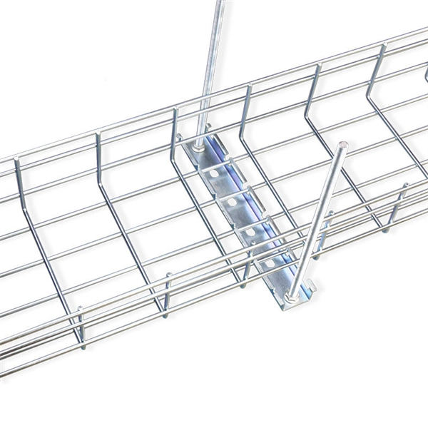
A ladder type cable tray tee is a fitting used to create a branch in a cable tray system, allowing cables to be routed in three directions. Its "T" shape provides a secure and efficient way to split cables from a main tray into two separate paths, ensuring organized and flexible. A cable tray tee and tee cover are components used in cable management systems to support and protect electrical and data cables. Here's a brief explanation of each:. Rigid steel cable tray tee fitting with zero tangent, safety bottom, and full accessory support. ventilation to heat producing cable such as power communication and other with the same or different width of the cable run. All fittings are available in sizes and types corresponding to the straight cable tray sections. These fitting are including: elbow, horizontal cross, vertical inside. NOTE : Equal or un equal tees can be supplied. When ordering state widths W1xW2xW3.. Office: 147/22 Nguyen Sy Sach Street, 15 Ward, Tân Binh Dist, HCMC,VN. Is it possible to connect 2 cabletrays with a "branch piece (left picture)" instead of a "tee (right picture)". The tee has 3 connectors, the branch piece only has 1 connector. I would like to ajust the "Type properties -> Fittings -> Tee" with the branch family, but can't get it accomplished.
[PDF]

Cable Trays* — Max two 24 in. (610 mm) wide by max 6 in. (151 mm) deep open-ladder cable tray with channel-shaped side rails formed of 0. 54 mm) thick aluminum or min 0. In practice, cable tray dimensions are a system of interrelated measurements —width, depth, length, and material thickness—that directly affect cable fill compliance, heat dissipation, structural loading, and long-term expandability. From an engineering standpoint, cable tray dimensions are not. Perforated Cable Tray System expertly constructed from high-grade stainless steel, offering exceptional durability and resistance to corrosion. With side height 100mm. A properly designed and installed cable tray system will provide. Studs — Wall framing to consist of wood studs or channel shaped steel studs. Wood studs to consist of nom 2 by 4 in. Additional studs shall be used to completely frame. Best Size: Here, deep trays (75mm to 150mm) are used since power cables are typically thick and heavy. Data cables, such as your Wi-Fi or computer ones, are extremely sensitive. They do not get hot; however, they do not like to hang or sag. In case a data cable folds in an excessive manner, the. ect the minimum bend ra-dius for cables as they exit the bottom of the cable tray. A rung spacing of 6 to 9 inches (150 to 230 mm) is preferable when the cable tray cont d for instrumentation and control applications that require additional protec eferred to support and protect numerous small.
[PDF]

This article provides a detailed technical comparison between fiber optic and copper cables, offering a clear perspective for engineers, network architects, and procurement managers. The core distinction between the two technologies lies in the physics of data. There are significant differences in performance between ADSS cables (all-dielectric self-supporting optical cables) and traditional optical cables, which are mainly reflected in the following aspects: 1. This type of fiber optic cable is designed to support its own weight without the need for additional support structures like messenger wires. The ADSS. There are several factors to assess when deciding which cable type is right for your application, including speed of connection for new customers, ease of changes and repairs, installer certification requirements, and the ability to expand the network over time. ADSS Fiber Optic Cables are a type of optical fiber cable designed specifically for. All-dielectric self-supporting (ADSS) cable is a type of optical fiber cable that is strong enough to support itself between structures without using conductive metal elements. It is used by electrical utility companies as a communications medium, installed along existing overhead transmission.
[PDF]

Use two fibers: one dedicated to TX, the other to RX. Both sides transmit and receive at the same wavelength (common values: 850 nm MM, 1310 nm/1550 nm SM). The front panel is usually labeled TX and RX, and you cross-connect TX→RX, RX→TX with a duplex patch cord. Switch optical port intercommunication means that the optical fiber ports of two switches are connected to each other to achieve the purpose of network connection. The connection between two or more Ethernet switches in a certain way (Uplink port, etc. ) is called the cascade. SFP modules insert into these slots and and require two strands of fiber, typically duplex Using multi mode fiber (for runs under 1000 feet) or duplex single mode fiber (for runs over 1000 feet). This is a cost-effective and high performance way to connect network switches. Use one fiber strand for both. The switch supports 10 Mbps, 100 Mbps, and 1000 Mbps connections. Using Gigabit Ethernet (1000 Mbps), the switch sends files across the network at speeds up of to 2000 Mbps due to the full-duplex nature of Gigabit Ethernet connections. You can either connect 24 Ethernet copper cables or 22 copper. Port types are limited to two: optical and Ethernet. Optical ports on switches typically accommodate optical modules for transmitting data via fiber optic cables. In situations where there's a shortage of Ethernet ports, some users may insert Ethernet port modules into optical ports to connect with.
[PDF]

While optical fiber forms the basis of data transmission, optical fiber cables serve as the infrastructure that facilitates the deployment and protection of these delicate strands. An optical fiber cable consists of one or more optical fibers . These cables are used mainly for digital audio connections between devices. A fiber-optic cable, also known as an optical-fiber cable, is an assembly similar to an electrical cable but containing one or more optical fibers that are used to carry light. The optical fiber elements are typically. There are different types of fiber optics based on several categories as mentioned below: 1. Based on the Number of Modes Single-mode fiber: In single-mode fiber, only one type of ray of light can propagate through the fiber. Connector types play a crucial role in selecting the right cable for specific applications, as different connectors are designed for various environments, space constraints, and high-bandwidth. Communication with fiber-optics has many advantages over electrical or “wire”-based interfaces. Unfortunately, fiber has often been considered an expensive or exotic solution, limited to high-end applications that absolutely require it. 770 references sections in Chapter 2 and Art. 300 do these apply to optical fiber cables and raceways [770. For example, subsection 770. 22, which applies when.
[PDF]

Find certified telecom, fiber optic, and copper cable splicing contractors in Georgia. Browse the SpliceList directory for verified splice crews. From homes to businesses, Comlink Solutions delivers reliable and efficient fiber optic infrastructure tailored to your specific needs. Our team of experts provides comprehensive services, from design and planning to splicing and installation. Trust us to deliver exceptional results. Over 30 years of expertise powering the nation's largest telecom networks. Turnkey fiber optic solutions from construction to testing — delivering excellence at every stage of the network lifecycle. FiberNexxt Communications, based in Marietta, Georgia, near Atlanta, is one of the area's experienced fiber splicing companies. We specialize in projects too small for large contractors and provide post-project support. Click the button below to get started. Professional fiber optic splicing services in Georgia with complete OSP overhead construction, strand deployment, pole engineering, splicing, testing, and full QA processes engineered to support telecom, ISP, and municipal broadband expansion across the state. Tired of fiber connectivity issues slowing down your business? Our expert fusion splicing services deliver rock-solid, high-speed connections for offices, warehouses, and data centers across Georgia and Atlanta. Slow internet again? Dropped connections during critical operations? Poor quality fiber.
[PDF]