The securing, storing and supporting of fiber optics and splices makes up an important step of fiber optic deployments in the field. Whether connecting to aerial or underground cables, telecommunication.
[PDF]

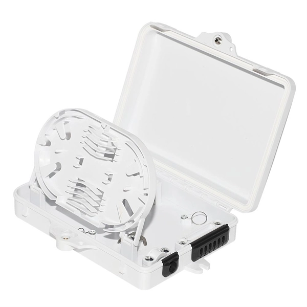
The main components of a splice box are the splice cassette that picks up the fibers and their reserves, and the front panel which contains different connectors for transmitting signals via copper or fiber optic cables. A splice box (also known as splice distributor) is a housing in which fiber optic cables begin or end. Fiber optics are fanned out in splice boxes that are situated at the end of fiber optic transmission paths. It typically consists of two parts: an outer housing and an internal structure. In this response, we will focus on the. The FSB series of indoor wall mount enclosures are designed for centralized splice-only applications. These boxes are well suited as optical cable splice collection points for DAS (Distributed Antenna Systems), MTU (Multi-Tenant Unit) commercial business applications, and MDU (Multi-Dwelling Unit). Fiber optic splice closures permanently connect two fiber optic cables together and have a splice that protects the components. The optical cable connection part, that is, the optical cable joint, is the part that protects the connection between two or more optical cables by the optical cable. Splicing refers to the permanent connection of two optical fibers to form a continuous optical connection.
[PDF]

Mass fusion splicing can fuse up to all 12 fibers in one ribbon at once. Entire ribbons can be spliced simultaneously. Standard mass-fusion color-coded pigtail kits contain a. Traditional Fusion Splice-On Connectors with pigtails provide factory-polished performance with field-termination convenience within harsh environments. com offers Less-Than-A-Truckload “LTL” option for products that cannot be shipped via parcel shipping. For products that will be shipped via LTL, you will be provided with a set of Accessorials to select from to provide Anixter with additional shipping considerations, such as. The Relevance Inspector will open in the Coveo Administration Console. SDX Pigtail Fusion Metal Splice Module pre-loaded with duplex LC adapters (Blue) and 12-fiber OS2 LC/UPC individual pigtails. Works with all SDX Enclosures. SDX 12- and 24-fiber splice modules protect and organize heat shrink fusion spliced fibers (up to 12 or 24 fibers) inside a fiber enclosure. The modular design enables faster field splicing and simple management of pigtails within the housing. The M4 Splice Cassette is designed for use with Single-Mode OS2 fiber, houses 12 fibers, and provides LC UPC Duplex ports.
[PDF]

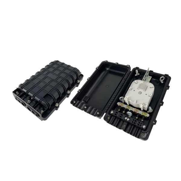
A typical fiber optic splice enclosure consists of several key components that work together to protect and organize the fiber splices. Standard enclosures contain: 1) Housing, 2) Cable fixation clamps, 3) Splice trays, 4) Sealing system. A splice box (also known as splice distributor) is a housing in which fiber optic cables begin or end. Fiber optics are fanned out in splice boxes that are situated at the end of fiber optic transmission paths. Optical cable joint box The optical cable joint box permanently connects two optical cables together and has a joint part for protecting components. The optical cable connection part, that is, the optical cable joint, is the part where the. An optical cable split fiber box, also known as a fiber distribution box or fiber optic splice closure, is a device used to terminate, splice, and distribute optical fibers. In this response, we will focus on the. This guide optimizes the original text by delving deeper into the three pillars of fiber network longevity: the impact of splicing technology, the strategic selection of splice boxes, and the essential maintenance protocols needed to ensure sustained, high-speed functionality. Fibre optic cables are manufactured in standardized lengths –.
[PDF]

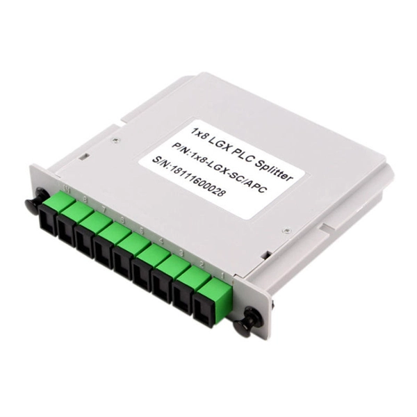
The Signal Fire Fiber Fusion Splicer AI-8C is a state-of-the-art fusion splicing toolbox kit designed for optical fiber and cable projects. The 8 port Fiber Distribution Box is sturdy in structure, lightweight in size, and easy to install. It can be installed on walls or utility poles, and its waterproof cover ensures maximum moisture protection, ensuring optimal performance in any weather conditions. This distribution box can connect. Check each product page for other buying options. Need help?. An 8-core fiber optic splice box is a critical component in fiber optic networks designed to protect spliced fiber cables, ensuring signal integrity and long-term reliability. These enclosures safeguard delicate fiber connections from environmental hazards, physical damage, and contamination. With the capacity to accommodate up to 8 subscribers, it serves as the termination point for the feeder cable. You can connect it with the drop cable. SPEED MEETS PRECISION - Experience lightning-fast splicing with a 6-second splice time and 15-second heating. VERSATILE FIBER HOLDER - Adaptable 3-in-1 holder for various fiber types, ensuring. The fiber distribution box is designed to realize the connection between outdoor optical fiber cable and pigtail or splitter, which can realize cable direct connection and branch connection in FTTH network. It offers the functions of fiber splicing, splitting, and distribution, apply to indoor and.
[PDF]
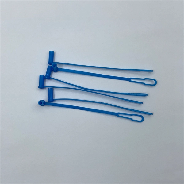
Fibre optic protection sleeves are essential for ensuring the long-term reliability and performance of fibre optic cables. Without these sleeves, the optical fibres are at risk of being damaged during installation or use, which can lead to signal loss, degradation, or even. A Fiber Optic Splice Sleeve is a protective tube designed to encase a fusion splice—the point where two optical fibers are joined together. After two fibers are precisely fused using a fusion splicer, the splice is fragile and needs protection from physical stress, moisture, dust, and other. A fiber optic cable protection sleeve is a specialized covering designed to safeguard optical fibers from physical damage, environmental hazards, and operational stress. Proper use of these sleeves ensures network reliability, extended service life, and lower maintenance costs, which is essential. People who belong to the world of fiber optics must have heard about fusion splice protection sleeves. In case the term 'fiber cable sleeve' is new to you, this blog is for you. Many companies claim that using these sleeves can lower maintenance costs. Composed of durable materials such as ceramic or metal, these sleeves shield connectors from external factors that could compromise signal quality.
[PDF]
Different networks have different needs when it comes to fiber optic joint closures. At Multilink, we have a variety of closures to meet these needs, including inline types and drop terminals. In our selection, you can find the following termination. Different networks have different needs when it comes to fiber optic joint closures. At Multilink, we have a variety of closures to meet these needs, including inline types and drop terminals. In our selection, you can find the following termination enclosures and splice boxes for use with different cable sizes and numbers of drops: Optima™: The Op. The securing, storing and supporting of fiber optics and splices makes up an important step of fiber optic deployments in the field. Whether connecting to aerial or underground cables, telecommunications companies rely on fiber optic closures to protect and facilitate fiber splices and regular maintenance in Fiber to the Home (FFTH) and other indoo. With more than 35 years of experience, Multilink is a leader in the telecommunications industry. We make innovative products and help our customers succeed by providing high-quality equipment that's laboratory tested and proven to perform. Telecommunications companies often have unique requirements for their equipment. If you have a specific fiber.
[PDF]
An improper cleaving angle can lead to uneven fibre surfaces, which makes it difficult for the fusion splicer to align the fibres. The cleaver should produce a perpendicular cut to the fibre to ensure proper alignment during splicing. Poor cleaving is one of the most common causes of poor splice results when using a fusion splicer. When cleaving isn't done correctly, it can lead to gaps, misalignment, or even an incomplete splice, which can compromise the integrity of your network. But fear not; there are simple troubleshooting. The performance of a fiber optic splice is determined by a number of factors, including the quality of the fiber, the cleanliness of the splice, and the techniques used to make the splice. Intrinsic factors, such as the refractive index of the fiber, are those that are inherent to the fiber itself. To counteract these errors, technicians can go through the following troubleshooting checklists: Perform an Arc Test: Before splicing, it's important to perform. One of the most frequent complaints among technicians is unexpectedly high splice loss. The root causes typically include: To resolve this, first. The fiber diameter appears reduced where the two fibers were joined. A “too thin” splice is typically caused by excessive stretching of the molten glass during the arc.
[PDF]

Mechanical splicing is a fast way to join two fiber optic cables. Instead, you line up the fibers inside a small holder made of plastic or metal. The holder keeps the fibers steady. A special gel helps light move through the joint. In this guide, we'll walk you through exactly how to splice fiber without a fusion splicer, covering the tools you need, the step-by-step process, performance specs, and common mistakes to avoid. By the end, you'll be equipped to make clean, low-loss connections in any field scenario. Experts who add quality contributions will have a chance to be featured. Learn more Mechanical splicing is a. Executive Summary: A fiber optic pigtail is one of the most commonly specified yet least understood components in structured cabling. Get the wrong connector type, the wrong polish, or skip proper fusion splicing technique—and you're looking at elevated signal loss, increased back reflection, and a. Fiber optic cable splicing connects two cables, creating a strong link for fast data transmission. Fusion splicing uses heat to join fibers, while mechanical splicing aligns fibers without the need. This video will show you how to repair a damaged fiber optic cable strand without a fusion splicer. This temporary fix will get your network back up and running, giving you time to source new fiber cable. Fusion Splicing Fusion.
[PDF]
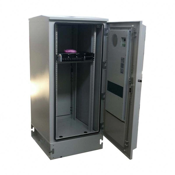
Abstract—This paper gives a general view on the current Access Network (AN) and the future options for the Libyan Optical Access Network (OAN) market. It starts by introducing the current broadband services demand in the country. An Optical Distribution Frame (ODF) is the central hub for fiber splicing, termination, patching, and cable protection in modern optical networks. As data centers, enterprises, telecom operators, and smart-building infrastructures deploy increasingly dense fiber links, ODFs provide the structured. Enter the Optical Distribution Frame (ODF)—a foundational component that serves as the “nerve center” for fiber optic management, enabling seamless connectivity, efficient maintenance, and scalable growth. This guide demystifies ODF, exploring their design, core functions, types, and how they. The Corning® Optical Distribution Frame is optimized for high-density cross-connect applications. When fully loaded with EDGE 4U housings the optical distribution frame dual-frame model provides a total capacity of 5,760 LC Duplex or MTP ports / 11,520 LC Simplex ports while the single-frame. In today's communication infrastructure, high speed, reliability, and manageability are at the core. Fiber optic communication technology plays a crucial role in meeting these demands. Moreover, ODFs provide a secure environment to protect.
[PDF]
I review the historical observation and subsequent research on optical soliton dynamics in gas-filled hollow-core optical fibres. The combination of hydrogen and short 40-fs input pulses underlies clean and efficient generation of Raman solitons between 1080 and 1600 nm. include both large-core hollow capillary fibres, and hollow-core photonic-crystal or microstructured fibres with smaller cores, in particular photonic bandgap and. Table-top coherent vacuum-ultraviolet (VUV) sources are important in many researches. Dispersive wave (DW) emission in a gas-filled hollow-core fiber (HCF) is an efficient way to obtain tunable VUV source with microjoule-level pulse energy.
[PDF]

Too many connections can cause too much signal loss. Clean your connections. As we discussed above, remove dirt, dust and oil from fingerprints with pen-style cleaners or alcohol wipes. Identify cable damage using a VFL tester. If identified, re-splice the cable. When issues like signal loss, slow speeds, or intermittent connectivity arise, systematic troubleshooting is key. This guide will walk you through diagnosing and resolving common fiber network issues efficiently. Why Do Fiber Networks Fail? Despite their robustness, fiber networks can fail due to:. Problems with fiber optic internet can range from signal attenuation to optic signal loss to equipment malfunctions. By shedding light on these common fiber internet problems and offering insights into preventative measures and advanced troubleshooting steps, we aim to empower network. Fiber optic troubleshooting is an essential skill for network administrators, technicians, and engineers responsible for maintaining and repairing fiber optic systems. These high-speed, high-capacity communication networks are increasingly replacing copper cables, offering superior performance and. Clean Fiber Optic connectors often to stop dirt and dust. Finding problems early saves money. It also stops long network downtime. Use the right tools to test for weak spots. These networks are the backbone of modern data transmission, offering incredible speeds and bandwidth.
[PDF]
Rayleigh scattering -based distributed acoustic sensing (DAS) systems use fiber optic cables to provide distributed strain sensing. In DAS, the optical fiber cable becomes the sensing element and measurements are made, and in part processed, using an attached optoelectronic device. These systems enable precise measurement of temperature, strain, and acoustic signals along the entire length of an optical fiber. DFOS technology plays a crucial. ONYXTM the flagship platform from Sintela now delivers a customizable all-in-one, simple and cost-effective solution for your distributed fiber-optic sensing needs. Representing the next step in the evolution of Distributed Fiber Sensing, ONYX™ converts existing telecommunications fiber-optic cable. Distributed acoustic sensing systems (DAS) are fiber optic based optoelectronic instruments which measure acoustic interactions along the length of a fiber optic sensing cable. The unique feature of a distributed acoustic sensing system is that it provides a continuous (or distributed) temperature. Distributed Acoustic Sensing (DAS) is a cutting-edge technology that uses optical fiber to sense and identify multiple parameters over extended distances remotely. The technology leverages the Rayleigh backscatter theory to detect vibrations and sounds along the fiber Fiber optic-based Distributed.
[PDF]
Single fiber modules (BiDi) use one fiber for both transmitting and receiving data. This saves space and money. They are easier to set up and give steady communication. They use. There are two main types of fiber optic cables: single mode and multimode. Although they can do the same job in some instances, the different construction methods make each of them better suited to certain tasks and budgets. That makes picking between single mode and multimode fiber optic cables an. Single mode fiber optic cable is made up of a small diameter glass or plastic core surrounded by cladding, which is a layer of reflective material. This small diameter core, typically around 9 microns in diameter, allows only one mode of light to pass through, resulting in a narrower beam of light. The secret lies in fiber optic technology, and understanding the basics—1-core, 2-core, Single Mode (SM), and Multi-mode (MM)—is key to mastering this field. Let's break down these terms in simple, clear language with practical examples. Definitions · 1-core vs. multimode fiber in depth, explaining their structure, working principles, standards, and performance characteristics so that. Unlike copper cables, which rely on electrical signals, fiber optics use pulses of light to transmit data—offering unmatched bandwidth, low interference, and long-distance capabilities. But not all fiber cables are created equal: multimode (MM) and single mode (SM) fibers are the two primary types.
[PDF]
Single mode fiber patch cord: Single mode 9/125um optic patch cord are designed for long-distance transmission. They have a smaller core diameter (typically 9 microns) compared to multimodeoptic.
[PDF]