
Multi-mode fiber optic patch cords utilize a larger core size, typically around 50-100 microns, allowing them to carry multiple modes of light. This design enables the transmission of data over relatively short distances with high bandwidth capabilities. A fiber-optic patch cord is a fiber-optic cable capped at each end with connectors that allow it to be rapidly and conveniently connected to telecommunication equipment. This is known as interconnect-style cabling. A fiber-optic patch cord is constructed from a core with a high refractive. These short fiber optic cords connect transceivers, switches, patch panels, and servers. Without them, even the best optical modules and switches cannot deliver performance. As data rates increase from 10G → 100G → 400G → 800G, patch cables must handle more bandwidth, more density, and stricter. Fiber optic patch cords, also known as fiber optic patch cables or fiber jumpers, are indispensable components in modern optical networks. They act as the critical link for interconnecting devices like optical switches, servers, and distribution frames. Understanding the various technical. Fiber patch cables, also called fiber-optic patch cords, are cables typically containing one or two optical fibers, which are equipped with standardized fiber connectors on both ends. The function of the fiber patch cord.
[PDF]

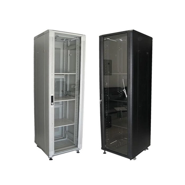
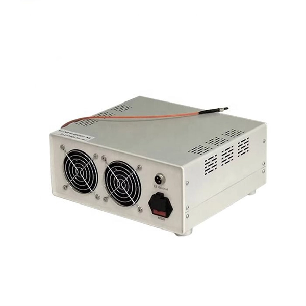
It connects to two independent power sources, enabling automatic switching to a secondary source during primary source failures. This seamless transition prevents disruptions to connected devices and enhances operational reliability. A dual power switching box is precisely the kind of gadget that guarantees a constant flow of electricity as it enables the user to shift the operational state between two different energy supplies. It can be found in homes, workplaces, factories, and anywhere else where sudden cuts of energy can. The ATS Dual Power Distribution Box plays a pivotal role in providing efficient low-voltage power solutions, ensuring that power flows seamlessly, even in the event of an outage. This comprehensive guide offers insights into the mechanisms and benefits of the ATS Dual Power Distribution Box. Transfer switches and sub panel boxes are key components in dual power switching cabinets. Transfer switches automatically switch between power sources during outages, ensuring uninterrupted power and system reliability. This redundancy ensures that if one power source fails, the other can immediately take over, minimizing downtime and preventing. A dual power switch helps you manage two power sources for one system. You can use it to keep your equipment working if the main power stops. This device quickly changes from the main supply to a backup source. This seamless transition.
[PDF]

At its core, a fiber termination box combines hardware and software components to facilitate fiber optic connections. The hardware includes protective enclosures, splice trays, adapters, connectors, and patch panels. A Fiber Terminal Box (FTB) is a customer-side termination and distribution device used at the end of the optical network. It is small, so it is considered a mini version of the optical distribution frame or optical distribution frame (ODF). The number of ports of fiber optic junction boxes ranges from 8. A fiber optic junction box, also known as a fiber optic distribution box or termination box, is a protective enclosure that facilitates the connection and management of fiber optic cables. It serves as a central point for organizing and distributing optical fibers, ensuring efficient connectivity. Fiber termination boxes are essential components in modern telecommunications infrastructure. They serve as the critical junction points where fiber optic cables connect, splice, and distribute data signals efficiently and securely. Here's a structured breakdown. This article provides an in-depth comparison of fiber terminal boxes and junction boxes to help clarify their differences and deepen your understanding.
[PDF]

A typical fiber optic splice enclosure consists of several key components that work together to protect and organize the fiber splices. Standard enclosures contain: 1) Housing, 2) Cable fixation clamps, 3) Splice trays, 4) Sealing system. A splice box (also known as splice distributor) is a housing in which fiber optic cables begin or end. Fiber optics are fanned out in splice boxes that are situated at the end of fiber optic transmission paths. Optical cable joint box The optical cable joint box permanently connects two optical cables together and has a joint part for protecting components. The optical cable connection part, that is, the optical cable joint, is the part where the. An optical cable split fiber box, also known as a fiber distribution box or fiber optic splice closure, is a device used to terminate, splice, and distribute optical fibers. In this response, we will focus on the. This guide optimizes the original text by delving deeper into the three pillars of fiber network longevity: the impact of splicing technology, the strategic selection of splice boxes, and the essential maintenance protocols needed to ensure sustained, high-speed functionality. Fibre optic cables are manufactured in standardized lengths –.
[PDF]
Laser diodes without feedback photodiodes are common in laser pointers, barcode scanners, CD/DVD/Blu-ray players, laser toys and simple alignment tools. The laser diode is an unsung hero of modern technology. Diode laser technology drives a. An example of an edge-emitting laser diode structure is shown in Figure 1. This type of structure is termed to as Fabry-Perot type laser. From the figure above, you can clearly see that a PN junction is formed by two layers of doped gallium arsenide (GaAs). Each type of laser diode is designed for specific applications, so choosing the right one ensures you achieve the best results for your needs. 3 Ready to find the perfect laser for your job?. A laser diode, manufactured by Electronic Spices, is a semiconductor device known for its ability to emit coherent light through a process called stimulated emission. Laser diodes are widely used in various applications such as fiber-optic communications, barcode readers, laser pointers. Laser diodes (LD) are semiconductor devices that convert electrical energy into high-power optical energy. These devices are currently used in the fields of telecommunications and medicine and in industrial cutting and welding applications. What is a Laser Diode? The term LASER stands for Light Amplification by Stimulated Emission of Radiation.
[PDF]
Optical amplifiers work differently. They amplify the light directly, with no conversions. This process is faster, more efficient, and keeps the signal clearer. Using optical amplifiers helps reduce signal distortion, lowers system costs, and supports long-distance communication. The most common types include: Erbium Doped Fiber Amplifiers (EDFA): EDFAs are the most commonly used type of optical amplifier in telecommunications. They play a vital role in modern optical communication systems, enabling the transmission of high-speed data over long-haul networks. An optical amplifier is a device that boosts the strength of an optical signal. 2dB per kilometer for 1. This means that over a distance of 100km, a signal can lose around 20dB. This principle dictates that a photon can interact with an atom already in an excited energy state, forcing the excited atom to immediately release its stored energy as a second photon. It does this without changing the light into an electrical signal. In the past, systems used repeaters to fix weak signals. These repeaters turned light into electricity, boosted the signal, and then. The SPIE Digital Library offers a comprehensive range of content on optical amplifiers, reflecting their significance in modern photonics and telecommunications. The library includes a variety of peer-reviewed papers, conference proceedings, and technical articles that delve into the fundamental.
[PDF]

Fiber optic loss calculation formula: Total link loss (LL) = Cable attenuation + Connector attenuation + Fusion attenuation [Note: If there are other components (such as attenuators), their attenuation values can be added]. Intrinsic Optical Fiber Losses comprise of absorption loss, dispersion loss and scattering loss caused by the structural defects. The detailed information about these optical losses and how to reduce them are. Calculate fiber optic signal loss based on cable length, attenuation, and connector losses. Determine cable loss, connector loss, and total system loss in decibels (dB) to assess signal quality and repeater requirements. Fiber optic loss is calculated in two parts: cable loss and connector loss. This calculator determines fiber loss based on input power, output power, and the length of the fiber optic cable. In summary, fiber optic loss is. Use this worksheet to input values for all variables that will impact your system's performance. After entering your values, please ensure you click the 'Calculate Link Loss' button at the bottom of the page to generate your total link loss. This step is necessary to see if your system falls within. Optical fiber loss is a term for signal loss affecting transmission reliability. Optical fiber loss is.
[PDF]

Sensitivity Test: Confirms that the protection works properly for internal defects in the protected zone. Inject primary current via one set of CTs, with one current flowing inward & the other outward. If the CTs are properly connected, there should be no operating current at the. A protective relay is basically an electrical device that detects a fault in a power system and initiates the operation of the circuit breaker to isolate the defective section or component from the rest of the system. In other words, the prime function of protective relays is the timely and. To conduct the tests effectively the following devices and equipment are required: Primary Injection Test Kit – for injecting large currents directly into CT circuits. Secondary Injection Test Kit – Simulates relay inputs with the controlled currents and voltages. It emphasizes selectivity, coordination, fault response, and system behavior rather than individual relay devices. This prevents damage to equipment, reduces downtime, and safeguards. This handbook covers the code of practice in protection circuitry including standard lead and device numbers, mode of connections at terminal strips, colour codes in multicore cables, dos and donts in execution. Its main purpose is to safeguard electrical equipment like transformers, generators, and transmission lines from damage due to.
[PDF]

Indoor armored fiber optic cable are the latest networking infrastructure need. The cables provide ultimate mechanical protection, fire protection, and ease of installation, and thus they are suitable for indoor applications such as offices, data centers, and homes as well. These cables are suitable for both indoor and outdoor applications. Other specialized metal designs include square lock armored, spiral. In environments with high crush risk, rodents, or moisture, standard cables are not enough. What is an Armored Fiber Optic Cable? An. Supported applications include gigabit, 10 gigabit, and 40 gigabit Ethernet. Unsure Which Cables Will Suit Your Needs? What speeds and applications will this indoor armored tight-buffered plenum cable support? With bend-insensitive optical fibers (except OM1), this armored fiber optic cable is. These indoor fiber optic cables are used exclusively within buildings and must have a flame-retardant cable jacket to fit this purpose. Flame resistant cable may be deployed in-duct (conduit) or cable tray. Right selection of. Armored fiber cable is a fiber optic cable reinforced with additional protective layers to enhance its durability and resistance to external damage. These cables are designed to endure extreme environmental conditions, physical strain, and potential interference. The armor typically consists of.
[PDF]
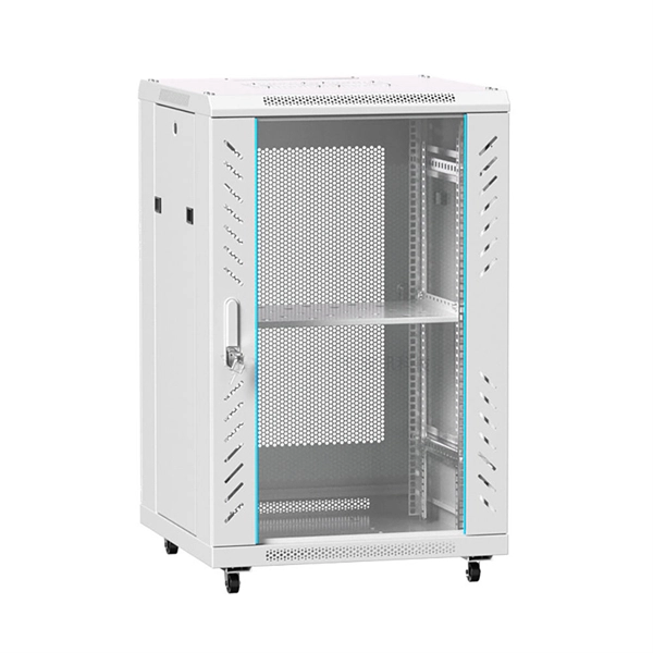
Through a real deployment case using E-abel server cabinets, we illustrate how cabinet design and connector architecture improve power reliability, reduce maintenance complexity, and support the increasing power density of modern data centers. Managing and installing a rack power distribution unit (PDU) has never been easier than with the EL2P PDU. Designed to simplify deployment and take stress out of power distribution, this intelligent PDU helps reclaim valuable hours. Whether that means speeding up Saturday installs or focusing on. An Intelligent Power Distribution Unit (iPDU), also known as a Smart PDU or Intelligent PDU, is a critical component in modern data center infrastructure. The units are available in horizontal 19-in. rack or vertical mounting capabilities. Why Has the Selection of Rack PDUs Become So Important?. For power distribution requirements of medium to large data centers, Delta's Power Distribution Unit (PDU) is an optimal solution. The space-saving PDU is easy to move and adapt to the future demands of the data center. The PDU offers superior power protection and monitoring, and the flexibility. Modern infrastructures typically rely on rack-level Power Distribution Units (PDUs), industrial CEE connectors, and structured cabinet designs to manage power connections efficiently. This article explores how power is connected inside modern data center racks, examining the flow of electricity.
[PDF]
In fiber optic circuit technology an optical fiber link is used for transferring digital or analogue data in the form light frequency through a cable which has a highly reflective central core. Internally, the optical fiber.
[PDF]
The principle of gap-loss is used in optical attenuators to reduce the optical power level by inserting the device in the fiber path using an inline configuration. Gap-loss attenuators are used to prevent the saturation of the receiver and are placed close to the transmitter. The basic types of optical attenuators are fixed, step-wise variable, and continuously variable. The attenuator circuit will allow a known source of power to be reduced by a predetermined factor, which is usually expressed as decibels. In fiber systems, attenuation is specified in dB (a ratio), while optical power is often given in dBm (absolute power referenced to 1 mW). If a transmitter outputs +3 dBm and. If you are still looking to reduce the signal power of optical fiber links, Optical Attenuators are undoubtedly a good choice and can bring you a good solution. Because the signal power of the optical fiber link is too high, it will cause abnormalities in the optical fiber network, so it is. A Variable Optical Attenuator (VOA) is a controllable device used to reduce the optical power traveling through a fiber or free-space optical path. Unlike a fixed attenuator, which imposes a constant loss, a VOA allows the loss to be adjusted from nearly zero up to tens of decibels. Understanding their principles is essential for their effective application. Optical attenuators work by absorbing or reflecting a portion of the optical signal, thus reducing its.
[PDF]
This relationship is mathematically described by the Beer-Lambert Law, which states that absorbance is directly proportional to the concentration of the substance and the distance the light travels through the solution. The more concentrated a colored solution is, the more light it. A colorimeter is a scientific instrument used to measure the absorbance of light by a colored solution to determine the concentration of solutes. The device operates on the principle that the intensity of the color is directly related to the amount of the colored. Instrumental color measurement moves beyond the limits of human perception and vocabulary and allows us to capture color information as objective data, creating a common language of color that is essential for communication within and between industries around the world, ranging from food and. Colorimeters are built for speed: These devices act as a quick translator for human vision. They are fast, budget-friendly, and perfect for routine pass/fail checks on the factory floor. This is the basis of colorimetry or.
[PDF]
Unlike a regular diode, the goal for a laser diode is to recombine all carriers in the I region, and produce light. Thus, laser diodes are fabricated using direct band-gap semiconductors.Component type, Working principle, Inventor, 1962; , 1962Pin names and Watch full videoOverviewA laser diode (LD, also injection laser diode or ILD or semiconductor laser or diode laser) is a device similar to a in which a diode pumped directly with electrical current can create. A laser diode is electrically a. The active region of the laser diode is in the intrinsic (I) region, and the carriers (electrons and holes) are pumped into that region from the N and P regions respectivel. Following theoretical treatments of M.G. Bernard, G. Duraffourg, and William P. Dumke in the early 1960s, light emission from a (GaAs) semiconductor diode (a laser diode) was demonstrat. The simple laser diode structure described above is inefficient. Such devices require so much power that they can only achieve pulsed operation without damage. Although historically important and easy to explain, such devic.
[PDF]

In this case use an optical power meter (OPM) and test the input port of the splitter for the optical power level (dBm) from the OLT at 1490 nm. If there is no or reduced power then the patchcord or OLT is the culprit. If the power level is reduced it could be as simple as a. So for this simple 1X2 splitter, how do we test it? Simply follow the same directions for a double-ended loss test. Attach a launch reference cable to the test source of the proper wavelength (some splitters are wavelength dependent), calibrate the output of the launch cable with the meter to set. Optical splitters in the outside plant (OSP) are used mostly in passive optical networks (PONs) for fiber-to-the-user (FTTx) networks, and are often overlooked as failure points. In this article I focus on a few basics of optical splitters, their applications, typical causes of failures, and how to. Now, we test the simplest 1x2 optical splitter as the picture shown below. 001 dB), OTDR (for reflection event detection). Cleaning tools. The CertiFiber® Pro Optical Loss Test Set (OLTS) can be used to check that the loss of a PON Splitter (often referred to in various standards as a non-wavelength-selective or wavelength-selective branching device) to check that it is within the allowed defined limits. The CertiFiber® Pro has an.
[PDF]
