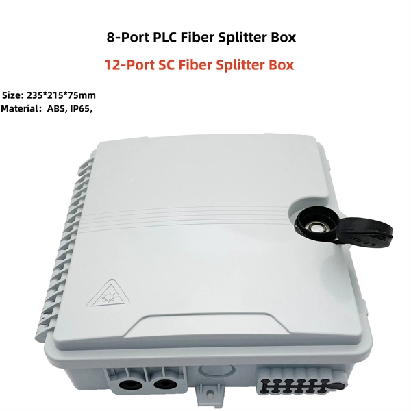
At its core, a fiber termination box combines hardware and software components to facilitate fiber optic connections. The hardware includes protective enclosures, splice trays, adapters, connectors, and patch panels. A Fiber Terminal Box (FTB) is a customer-side termination and distribution device used at the end of the optical network. It is small, so it is considered a mini version of the optical distribution frame or optical distribution frame (ODF). The number of ports of fiber optic junction boxes ranges from 8. A fiber optic junction box, also known as a fiber optic distribution box or termination box, is a protective enclosure that facilitates the connection and management of fiber optic cables. It serves as a central point for organizing and distributing optical fibers, ensuring efficient connectivity. Fiber termination boxes are essential components in modern telecommunications infrastructure. They serve as the critical junction points where fiber optic cables connect, splice, and distribute data signals efficiently and securely. Here's a structured breakdown. This article provides an in-depth comparison of fiber terminal boxes and junction boxes to help clarify their differences and deepen your understanding.
[PDF]

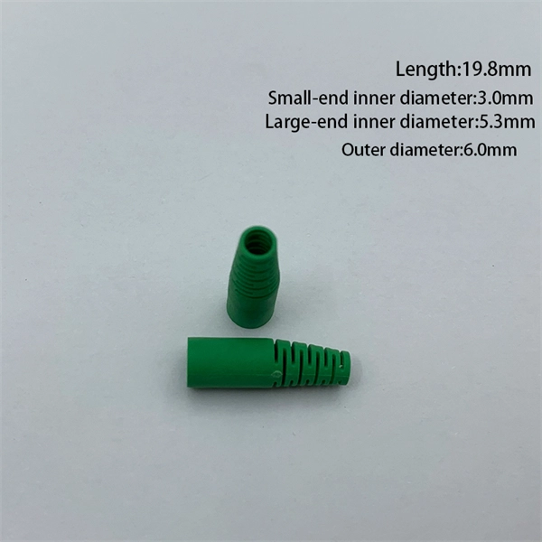
A typical fiber optic splice enclosure consists of several key components that work together to protect and organize the fiber splices. Standard enclosures contain: 1) Housing, 2) Cable fixation clamps, 3) Splice trays, 4) Sealing system. A splice box (also known as splice distributor) is a housing in which fiber optic cables begin or end. Fiber optics are fanned out in splice boxes that are situated at the end of fiber optic transmission paths. Optical cable joint box The optical cable joint box permanently connects two optical cables together and has a joint part for protecting components. The optical cable connection part, that is, the optical cable joint, is the part where the. An optical cable split fiber box, also known as a fiber distribution box or fiber optic splice closure, is a device used to terminate, splice, and distribute optical fibers. In this response, we will focus on the. This guide optimizes the original text by delving deeper into the three pillars of fiber network longevity: the impact of splicing technology, the strategic selection of splice boxes, and the essential maintenance protocols needed to ensure sustained, high-speed functionality. Fibre optic cables are manufactured in standardized lengths –.
[PDF]

It connects to two independent power sources, enabling automatic switching to a secondary source during primary source failures. This seamless transition prevents disruptions to connected devices and enhances operational reliability. A dual power switching box is precisely the kind of gadget that guarantees a constant flow of electricity as it enables the user to shift the operational state between two different energy supplies. It can be found in homes, workplaces, factories, and anywhere else where sudden cuts of energy can. The ATS Dual Power Distribution Box plays a pivotal role in providing efficient low-voltage power solutions, ensuring that power flows seamlessly, even in the event of an outage. This comprehensive guide offers insights into the mechanisms and benefits of the ATS Dual Power Distribution Box. Transfer switches and sub panel boxes are key components in dual power switching cabinets. Transfer switches automatically switch between power sources during outages, ensuring uninterrupted power and system reliability. This redundancy ensures that if one power source fails, the other can immediately take over, minimizing downtime and preventing. A dual power switch helps you manage two power sources for one system. You can use it to keep your equipment working if the main power stops. This device quickly changes from the main supply to a backup source. This seamless transition.
[PDF]

Multi-mode fiber optic patch cords utilize a larger core size, typically around 50-100 microns, allowing them to carry multiple modes of light. This design enables the transmission of data over relatively short distances with high bandwidth capabilities. A fiber-optic patch cord is a fiber-optic cable capped at each end with connectors that allow it to be rapidly and conveniently connected to telecommunication equipment. This is known as interconnect-style cabling. A fiber-optic patch cord is constructed from a core with a high refractive. These short fiber optic cords connect transceivers, switches, patch panels, and servers. Without them, even the best optical modules and switches cannot deliver performance. As data rates increase from 10G → 100G → 400G → 800G, patch cables must handle more bandwidth, more density, and stricter. Fiber optic patch cords, also known as fiber optic patch cables or fiber jumpers, are indispensable components in modern optical networks. They act as the critical link for interconnecting devices like optical switches, servers, and distribution frames. Understanding the various technical. Fiber patch cables, also called fiber-optic patch cords, are cables typically containing one or two optical fibers, which are equipped with standardized fiber connectors on both ends. The function of the fiber patch cord.
[PDF]

These regulations may be called Bangladesh Energy Regulatory Commission (Electricity Grid Code) Regulations, 2018 or in short Grid Code. These regulations shall come into force from the date of publication in the official gazette. INTRODUCTION. Title. “Schedule” means the schedule of these Regulations. The Grid Code shall apply in the field of electricity transmission system planning, connection conditions. Bangladesh Energy Regulatory Commission ELECTRICITY GRID CODE 2019 Effective Date: March _ _, 2019 Electricity Grid Code 2019 Bangladesh Energy Regulatory Commission NOTIFICATION Dated: March _ _, 2019 In exercise of the powers conferred by section 59 of the Bangladesh Energy Regulatory Commission. These regulations may be called Bangladesh Energy Regulatory Commission (Electricity Grid Code) Regulations, 2018 or in short Grid Code. INTRODUCTION In exercise. Wherever you are, BANGLAMARK is your reliable partner for the one-stop planning and construction of customized, state-of-the-art high-voltage substations. For power grid operators and utility companies the reliability of their power transmission and distribution equipment installed in their network.
[PDF]
Nauru's Online Legal database contains copies of Nauruan legislation (Acts and Subsidiary legislation), court decisions, gazettes and other relevant documents. Copyright 2023 — Ronlaw. Developed & Maintain by Digitity - Powered by Datec DocSearch™ Enhanced Search. The XL type low-voltage power distribution cabinet uses domestically designed new components. The enclosure is made of bent steel plates, featuring a compact structure, easy maintenance, and flexible circuit scheme combinations. Besides air circuit breakers and fuses for circuit protection, the. Access the most up to date content in ISO standards, graphical symbols, codes or terms and definitions. Preview content before you buy, search within documents and easily navigate between standards. RONLAW stands for Republic Of Nauru Law. Developed &. Frequency, voltage and meter accuracy standards 8. of a public supplier's works 9. Promotion of efficiency and economy 10. Codes of Practice 11. Location of meter box 13. Conductors from isolator switch to. REV. The online standards review database has been updated to provide greater functionality, offering a single sign in feature with dashboard, so users can easily access and highlight those items that require attention. The new system reduces staff and volunteer time by allowing committees to do all of.
[PDF]
Introducing the BS EN IEC 61439-3:2024, the latest standard for low-voltage switchgear and controlgear assemblies, specifically designed for distribution boards intended to be operated by ordinary persons (DBO). There are specific rules and standards for installation, handling and maintenance of machines and devices. Every German and European standard has to be approved by a series of institutions, including the "International Electrotechnical Commission (IEC)", the European comittee for electrotechnical. IEC Standards help in the measuring of that loss. With rapidly increasing global population and the industrialization of developing countries, comes soaring demand for energy – particularly electric power. According to the International Energy Agency (IEA), by 2040 global energy needs will have. IEC 61439-3 Ed. What Is the Purpose of a Distribution Board? An. The IEC (International Electrotechnical Commission) and BS 7671 (British Standard for Electrical Installations) both provide essential requirements for electrical installations, including those for fuse boards like garage unit, consumer unit and distribution board. While the IEC 60364 standard. We would like to hear your views on this material or activity. Please click here to provide your feedback. The publication cannot be displayed in the document viewer.
[PDF]
Fiber optic patch panels are enclosures that act as a distribution hub for fiber cable. A bulk (multi-strand) fiber cable enters the patch panel and then each fiber strand is separated into individual strands or pairs of strands. Fiber optic communications has been a rapidly expanding industry for the last 20 years. In its early years, it was mainly used for backhaul communications between large ISP's. But now fiber is widely used and can be found almost anywhere. It's probably in your ofice, on the telephone poles outside. A fiber patch panel is a mounted enclosure—either rack-mounted or wall-mounted—used to terminate, manage, and interconnect multiple fiber optic cables. It acts as a hub for organizing splices and patch cords, streamlining fiber management and preserving signal integrity. It provides a central point where incoming fiber cables can be connected to outgoing patch cords, making the network structured, accessible, and easy to maintain. This makes it easier to alter or troubleshoot the connections as they act as a central point where. Fiber patch panels play an increasingly important role in the optical fiber network due to the widespread use of high-density cabling systems in data centers. They are available in various fiber connector types, such as LC patch panel, SC patch panel and MTP patch panel. This article explores the structure, functionality, types, and benefits of fiber optic patch panels. What's the Fiber Optic Patch.
[PDF]
CWDM operates on the principle of wavelength multiplexing, where distinct wavelengths carry separate data streams. Each wavelength serves as an independent channel, enabling the transmission of various signals without interference. Here's a breakdown of the process:. In fiber-optic communications, wavelength-division multiplexing (WDM) is a technology which multiplexes a number of optical carrier signals onto a single optical fiber by using different wavelengths (i., colors) of laser light. Learn all about CWDM, how it differs from DWDM, and whether a CWDM solution is right for your business's network. This effectively increases the fiber's capacity, allowing more data to be. The focus of this paper is on the basics of designing and deploying Coarse Wavelength Division Multiplexing (CWDM) systems based on modular Wave-Division-Multiplexing (WDM) technologies and pre-connectorized (“plug-and-play”) solutions. Coarse Wavelength Division Multiplexing (CWDM) is a proven. By comparing CWDM vs DWDM vs MWDM vs LWDM vs SWDM, you can make an informed decision to ensure your network meets your data capacity, distance, and application requirements. As a key offshoot of WDM technology, CWDM (Coarse Wavelength Division Multiplexing) has been widely used in specific scenarios due to its low cost and ease of deployment. Below, ETU will provide a detailed analysis of CWDM, including its definition, operating principles, key characteristics.
[PDF]
Unlike a regular diode, the goal for a laser diode is to recombine all carriers in the I region, and produce light. Thus, laser diodes are fabricated using direct band-gap semiconductors.Component type, Working principle, Inventor, 1962; , 1962Pin names and Watch full videoOverviewA laser diode (LD, also injection laser diode or ILD or semiconductor laser or diode laser) is a device similar to a in which a diode pumped directly with electrical current can create. A laser diode is electrically a. The active region of the laser diode is in the intrinsic (I) region, and the carriers (electrons and holes) are pumped into that region from the N and P regions respectivel. Following theoretical treatments of M.G. Bernard, G. Duraffourg, and William P. Dumke in the early 1960s, light emission from a (GaAs) semiconductor diode (a laser diode) was demonstrat. The simple laser diode structure described above is inefficient. Such devices require so much power that they can only achieve pulsed operation without damage. Although historically important and easy to explain, such devic.
[PDF]

Summary : Fiber optic cables use light pulses to transmit data through ultra-thin glass or plastic strands, offering high-speed, long-distance communication. These cables rely on components like the core, cladding, strength member, coating, and outer jacket. These systems transmit digital information as rapid pulses of light through incredibly thin strands of pure glass, rather than as electrical current through metal wires. Multimode fibres operate primarily at 850 nm and sometimes at 1300 nm slightly different speeds. This is how optical prisms work Note: Forward Error Correction (FEC) is used to maximise link length for a given bit error. Optical fiber communication systems have become the cornerstone of modern telecommunications over the past four decades. As the demand for high-speed, high-capacity data transmission continues to grow exponentially, these systems have become increasingly essential. Harnessing the power of light. This is the FOA's Online Guide To Fiber Optics, Fiber Broadband & Premises Cabling. They operate on the principle of total. Designing a fiber optic network is like planning a city's road system, it needs to be efficient, reliable, and built to handle both current and future traffic. This fundamental aspect of modern infrastructure connects our homes, businesses, and communities to the digital world. Whether you're new.
[PDF]
A beam splitter or beamsplitter is an that splits a beam of into a transmitted and a reflected beam. It is a crucial part of many optical experimental and measurement systems, such as, also finding widespread application in.
[PDF]

Fiber optic connectors can be categorized according to different standards such as utilization, fiber count, fiber mode, and transmission method. They are also divided into single-mode and multimode types based on their distinct characteristics. This guide will walk you through the most common fiber connector types, explaining their characteristics, advantages, and typical use cases. Whether you're planning an FTTH deployment, upgrading a data center, or working in telecom infrastructure, this guide will help you make informed decisions. Compared to Copper cables, Fiber connector types are incredibly varied. Where copper twisted pairs tend to terminate with an RJ45 plug, fiber optic connectors come in all sorts of shapes and sizes, with all manner of different use cases in mind. An optical fiber connector is used to join optical. With a wide variety of connector types available, choosing the right connector for your network can be challenging. Learn how each connector works, where it's used, and how to choose the right option for today's high-density, high-speed networks. It is a precise coupling device that joins fiber optic cables quickly, enabling faster connection and disconnection than splicing. The connector mechanically orients the fiber cores, allowing light to pass and travel through. In this guide, you'll explore various types of fiber optic cable connectors, each with unique features and best uses. We'll also provide practical advice.
[PDF]

Beam splitters are classified by construction (plate, cube, pellicle, polka dot) and by function (standard, non-polarizing, polarizing, dichroic). Construction determines ghosting, damage threshold, and form factor. Function determines how polarization and wavelength are. Beamsplitters are optical components used to split incident light at a designated ratio into two separate beams. Additionally, beamsplitters can be used in reverse to combine two different beams into a single one. Beamsplitters are often classified according to their construction: cube or plate. A beam splitter (or beamsplitter, power splitter) is an optical device which can split an incident light beam (e. a laser beam) into two (or sometimes more) beams, which may or may not have the same optical power (radiant flux). It is a crucial part of many optical experimental and measurement systems, such as interferometers, also finding widespread application in fibre optic telecommunications. It is also possible to combine the separated beams. Types of Beam Splitters 2. They are found in different configurations and can be used in multiple applications. However, how they work exactly often remains overlooked. These versatile tools can split both laser and regular light, depending on the application in question.
[PDF]
Discover the most common types and models of Direct Attach Cables (DACs), including 10G, 25G, 40G, 100G, 200G, and 400G. A Direct Attach Cable (DAC) is a factory-assembled high-speed copper cable with fixed connector “module-style” ends. It's widely used for short-reach links in data centers because it delivers low latency, simple deployment, and cost-efficient interconnects-especially for rack-level connectivity. These cables come pre-terminated with SFP (Small Form-factor Pluggable) or QSFP (Quad Small Form-factor Pluggable) connectors which simplify network setup. High-speed cable is a kind of low-cost short-distance connection solution to replace optical modules. Both of its ends have cable assemblies of a module, which are connected. Direct attach copper (DAC) cables are twinax copper assemblies with fixed transceiver-like ends. They deliver high bandwidth, low latency, and great density for top-of-rack (ToR), server-to-switch and switch-to-switch connections. This article summarizes the common DAC categories and. What is a Direct Attach Copper (DAC) Cable? Common Types And Uses Summary : Direct Attach Copper (DAC) cables provide fast, reliable, and cost-effective short-distance connections for data centers, enterprise networks, and top-of-rack setups. With passive and active variants, DAC cables offer.
[PDF]