Unlike a regular diode, the goal for a laser diode is to recombine all carriers in the I region, and produce light. Thus, laser diodes are fabricated using direct band-gap semiconductors.Component type, Working principle, Inventor, 1962; , 1962Pin names and Watch full videoOverviewA laser diode (LD, also injection laser diode or ILD or semiconductor laser or diode laser) is a device similar to a in which a diode pumped directly with electrical current can create. A laser diode is electrically a. The active region of the laser diode is in the intrinsic (I) region, and the carriers (electrons and holes) are pumped into that region from the N and P regions respectivel. Following theoretical treatments of M.G. Bernard, G. Duraffourg, and William P. Dumke in the early 1960s, light emission from a (GaAs) semiconductor diode (a laser diode) was demonstrat. The simple laser diode structure described above is inefficient. Such devices require so much power that they can only achieve pulsed operation without damage. Although historically important and easy to explain, such devic.
[PDF]

A fiber optic ring network is a physical or logical network topology where devices (usually switches) are connected in a closed-loop using fiber optic cables. Each node is connected to two other nodes, forming a ring-like structure. This design ensures data can travel in both. This guide walks you through everything you need to know about fiber ring networks—from basic concepts to topology diagrams and essential protocols. Instead of running in a straight line from one point to another, the fiber forms a circular pathway linking multiple nodes. The. An example of this is the SONET/SDH (Synchronous Optical Networking/Synchronous Digital Hierarchy) dual-ring architecture, commonly used in telecommunications. A Metro ring refers to a fiber ring that covers a metropolitan area, connecting multiple locations such as data centers, offices, and. A fiber ring is a specialized configuration of a fiber optic network that arranges the physical transmission lines into a closed loop, or a ring. Data travels around this loop from one device to the next until it reaches its destination. It's one of the fundamental ways to organize a local area network, and while it's less. Network reliability and robustness are critical factors for any organization in the digital age. One approach that has proven effective in achieving these goals is using a fibre ring topology by running multiple redundant geographically different fibre paths to the cabinet. Fibre loops, also known.
[PDF]

Summary : Fiber optic cables use light pulses to transmit data through ultra-thin glass or plastic strands, offering high-speed, long-distance communication. These cables rely on components like the core, cladding, strength member, coating, and outer jacket. These systems transmit digital information as rapid pulses of light through incredibly thin strands of pure glass, rather than as electrical current through metal wires. Multimode fibres operate primarily at 850 nm and sometimes at 1300 nm slightly different speeds. This is how optical prisms work Note: Forward Error Correction (FEC) is used to maximise link length for a given bit error. Optical fiber communication systems have become the cornerstone of modern telecommunications over the past four decades. As the demand for high-speed, high-capacity data transmission continues to grow exponentially, these systems have become increasingly essential. Harnessing the power of light. This is the FOA's Online Guide To Fiber Optics, Fiber Broadband & Premises Cabling. They operate on the principle of total. Designing a fiber optic network is like planning a city's road system, it needs to be efficient, reliable, and built to handle both current and future traffic. This fundamental aspect of modern infrastructure connects our homes, businesses, and communities to the digital world. Whether you're new.
[PDF]

This article describes the anti-pumping relay, its definition, function, and circuit diagram. In a circuit breaker it is desired that when close and trip operation is performed on the circuit breaker with the closing coil energized, the subsequent closing operation should be prevented. So let's. Anti-Pumping relay is nothing but a NO contact, which means when the circuit breaker in closed condition the relay will be as NO point and if the circuit breaker in open condition the relay will be as NC Condition. The anti-pumping relays is connected in series with the circuit. An anti pumping relay (also called antipumping relay or Y-relay and ANSI 94 Trip or Trip-Free Relay) is a protective device that prevents a circuit breaker from closing repeatedly when a continuous close command is present. In simple terms, it stops your circuit breaker from “pumping” – which means. Anti-pumping relays are used in circuit breakers to prevent the breaker from closing unexpectedly after tripping. If the TNC switch fails (Trip normal close) or there is any problem with the CB (circuit breakers) closing circuit, the continuous CB (circuit breakers) close command can be extended to. Why is the Anti-Pumping Relay Used? A circuit breaker is a very important equipment for a high-voltage power system. It protects the system from high current or voltage during a faulty condition.
[PDF]
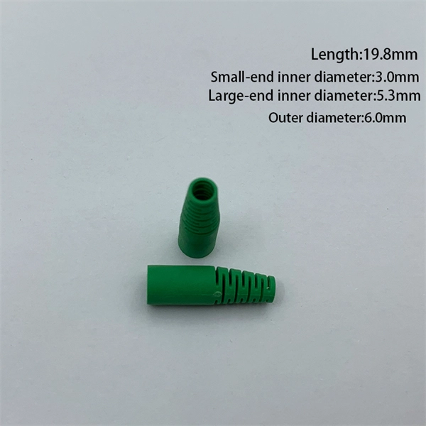
An optical junction box is a vital component in fiber optic networks. It serves as a termination point for fiber optic cables, providing protection and distribution of the optical fibers while ensuring efficient signal transmission. Optical cable junction boxes play a crucial role in connecting and protecting optical fibers, directly influencing the quality and lifespan of optical cable routes. As the demand for high-speed internet and reliable telecommunications increases, the. What is an optical cable splice box Optical cable splice box is a popular name, its scientific name is optical cable splicing box, also known as optical cable splicing package, optical cable splicing package and gun barrel. It belongs to the mechanical pressure sealing joint system and is a splice. --- Optical Fibre Junction Boxes are critical components in the realm of telecommunications, serving as the interfacing point for optical networks.
[PDF]
A beam splitter or beamsplitter is an optical device that splits a beam of light into a transmitted and a reflected beam. It is a crucial part of many optical experimental and measurement systems, such as interferometers, also finding widespread application in fibre optic telecommunications. DesignsIn its most common form, a cube, a beam splitter is made from two triangular glass which are glued together at their base using polyester,, or urethane-based adhesives. (Before these synthetic,. Beam splitters are sometimes used to recombine beams of light, as in a. In this case there are two incoming beams, and potentially two outgoing beams. But the amplitudes. For beam splitters with two incoming beams, using a classical, lossless beam splitter with Ea and Eb each incident at one of the inputs, the two output fields Ec and Ed are linearly related to the inputs thro.
[PDF]
This guide provides a comprehensive engineering perspective on ODFs—beyond the basic “what is an ODF” explanation—covering structural design, fiber management, MPO/MTP integration, and selection criteria for modern high-density deployments. Why ODFs are the Foundation of. This complete guide explores everything you need to know about ODFs — from their structure, types, and key components, to installation best practices and modern design trends. Whether you're building a central office, data center, or FTTx distribution network, understanding the right ODF. In the complex architecture of fiber optic networks, the Optical Distribution Frame (ODF) serves as the linchpin for organizing, protecting, and distributing optical signals. As data centers, enterprises, telecom operators, and smart-building infrastructures deploy increasingly dense fiber links, ODFs provide the structured. An ODF is a central hub in fiber optic networks, crucial for managing and organizing the variety of fiber-optic cables and connections entering a facility such as a telco central office (CO). They provide efficient fiber optic management, connectivity, and protection. What is Optical Distribution Frame An Optical Distribution Frame (ODF) is the central hub of your fiber optic network.
[PDF]

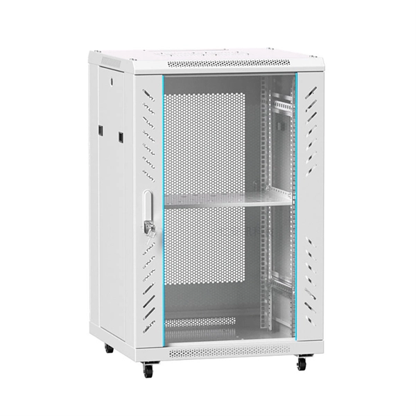
In this guide, you will learn how to interpret network diagrams like a pro, from symbols and scope to segmentation, dependencies, troubleshooting, and security clues. A rack elevation diagram is a visual representation of the equipment and components contained within a rack in a data center or server room. It provides a clear overview of the physical layout of the rack, including the placement and positioning of servers, switches, storage devices, and other. Learn how to read and interpret network diagrams effectively to troubleshoot, validate security, and plan network changes with confidence. Have you ever opened a network diagram and felt like you were staring at a subway map with no station names? That is a common problem, even for experienced IT. Network cabinet cabling describes the structured connection and arrangement of all IT components in a server rack. The aim is a secure, maintainable and scalable operation of the network environment. The amount. A standard operating procedure, or SOP, is a set of step-by-step instructions compiled by an organization to help workers carry out complex routine operations. Work instructions should be very detailed on "how" to accomplish a specific job, task or assignment. It helps teams understand network architecture, data flow, and dependencies, making it easier to design infrastructure, troubleshoot issues, and plan.
[PDF]

At its core, a fiber termination box combines hardware and software components to facilitate fiber optic connections. The hardware includes protective enclosures, splice trays, adapters, connectors, and patch panels. A Fiber Terminal Box (FTB) is a customer-side termination and distribution device used at the end of the optical network. It is small, so it is considered a mini version of the optical distribution frame or optical distribution frame (ODF). The number of ports of fiber optic junction boxes ranges from 8. A fiber optic junction box, also known as a fiber optic distribution box or termination box, is a protective enclosure that facilitates the connection and management of fiber optic cables. It serves as a central point for organizing and distributing optical fibers, ensuring efficient connectivity. Fiber termination boxes are essential components in modern telecommunications infrastructure. They serve as the critical junction points where fiber optic cables connect, splice, and distribute data signals efficiently and securely. Here's a structured breakdown. This article provides an in-depth comparison of fiber terminal boxes and junction boxes to help clarify their differences and deepen your understanding.
[PDF]
A beam splitter or beamsplitter is an that splits a beam of into a transmitted and a reflected beam. It is a crucial part of many optical experimental and measurement systems, such as, also finding widespread application in.
[PDF]
Through a real deployment case using E-abel server cabinets, we illustrate how cabinet design and connector architecture improve power reliability, reduce maintenance complexity, and support the increasing power density of modern data centers. Managing and installing a rack power distribution unit (PDU) has never been easier than with the EL2P PDU. Designed to simplify deployment and take stress out of power distribution, this intelligent PDU helps reclaim valuable hours. Whether that means speeding up Saturday installs or focusing on. An Intelligent Power Distribution Unit (iPDU), also known as a Smart PDU or Intelligent PDU, is a critical component in modern data center infrastructure. The units are available in horizontal 19-in. rack or vertical mounting capabilities. Why Has the Selection of Rack PDUs Become So Important?. For power distribution requirements of medium to large data centers, Delta's Power Distribution Unit (PDU) is an optimal solution. The space-saving PDU is easy to move and adapt to the future demands of the data center. The PDU offers superior power protection and monitoring, and the flexibility. Modern infrastructures typically rely on rack-level Power Distribution Units (PDUs), industrial CEE connectors, and structured cabinet designs to manage power connections efficiently. This article explores how power is connected inside modern data center racks, examining the flow of electricity.
[PDF]
In fiber optic circuit technology an optical fiber link is used for transferring digital or analogue data in the form light frequency through a cable which has a highly reflective central core. Internally, the optical fiber.
[PDF]

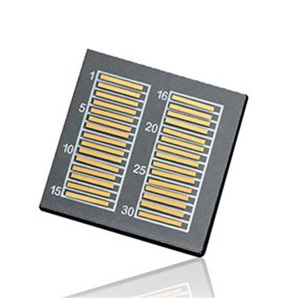
This page describes the structure, working operation, advantages, and disadvantages of a Fiber Bragg Grating (FBG) Sensor. Fiber optic sensors work by modulating one or more properties of the light wave, such as intensity, phase, polarization, and frequency. Fiber Bragg grating (FBG) sensors have emerged as advanced tools for monitoring a wide range of physical parameters in various fields, including structural health, aerospace, biochemical, and environmental applications. This review provides a comprehensive overview of FBG sensor technology. A fiber Bragg grating (FBG) is a type of distributed Bragg reflector constructed in a short segment of optical fiber that reflects particular wavelengths of light and transmits all others. An optical fiber typically consists of a. Abstract: Fiber grating sensors are more stable, more reliable and more accurate than traditional electromechanical sensors in many aspects. It can be used to sense and measure physical quantities such as stress, strain or temperature with high sensitivity and measurement range. In this paper, the. Optical fiber sensors (OFS) appeared just after the invention of the practical optical fiber by Corning Glass Works in 1970, now Corning Incorporated, that produced the first fiber with losses below 20 dB/km. At the beginning of this era, optical devices such as laser, photodetectors and the.
[PDF]