There are two main types of optical splitters based on manufacturing techniques: Fused Biconic Taper (FBT) splitter and Planar Lightwave Circuit (PLC) splitter. Optical splitters and couplers split or combine light—distributing signals injected into a single fiber strand to multiple fibers, enabling point to multi-point communication in Fiber To The Home (FTTH) networks based on ITU. T PON standards such as GPON, XGS-PON and new 25 and 50G standards. Optical splitters, also known as fiber optic splitters, are integral components in fiber optic networks, enabling one fiber input to be divided into multiple outputs. This capability is crucial in telecommunications, especially in Passive Optical Networks (PONs), where fiber-optic networks must. FS PLC Fiber Optic Splitters, Bare/Blockless/ABS/LGX Splitter/Rack Mount Types, support 1xN light distribution, with low IL and PDL for high-reliability transmission. Deploying compact FS PLC Splitters to simplify your networks, perfectly fits your PON, EPON, FTTX, etc. Conversely, it can also combine multiple signals into one. Unlike active devices (which require power), splitters operate without electricity, relying solely on the physics of. Fiber optic splitter is a passive optical device used to distribute optical signals, which can divide input optical signals into multiple outputs to meet the fiber optic access needs of multiple terminal devices.
[PDF]

Optical return loss is the amount of light that is reflected back to the source, this reflected light is measured at each connector and splice at each point over the entire fiber link. This is always measured in dB (decibels) and will be displayed as a negative number. The closer the number is to. The polish of a singlemode fiber endface plays a significant role in reflectance. Understand what you need before you specify. The Institute of Electrical and Building the ORL story Electronics Engineers (IEEE) recently Within a fiber-optic channel or path-released new specifications within way. Optical Return Loss (ORL) in fiber optics refers to the amount of light that is reflected back toward the source in a fiber link. ORL is usually expressed in decibels (dB) as a positive value, with. Return loss (RL) is also called reflection loss. When high-speed signals enter or exit a part of an optical fiber, such as an optical fiber connector, discontinuity and impedance mismatch may cause reflection, which is the return loss of an optical fiber. Poor ORL is commonly caused by dirty connectors, poor splices, mismatched connector types, or damaged fibers. ORL is measured using ORL meters. Home Coherent Optics Optical Return Loss (ORL) Explained Comprehensive Guide to Understanding and Managing Back-Reflections in Fiber Optic Systems What is Optical Return Loss (ORL)? Optical Return Loss (ORL) is a critical parameter in fiber optic systems that quantifies the amount of light.
[PDF]
The communication system of fiber optics is well understood by studying the parts and sections of it. The major elements of an optical fiber communication system are shown in the following figure. The ba.
[PDF]
A grid networks consist of an interconnected grid of circuits, energized from several primary feeders through distribution transformers at multiple locations. Grid networks are typically featured in.
[PDF]

Fiber optic connectors can be categorized according to different standards such as utilization, fiber count, fiber mode, and transmission method. They are also divided into single-mode and multimode types based on their distinct characteristics. This guide will walk you through the most common fiber connector types, explaining their characteristics, advantages, and typical use cases. Whether you're planning an FTTH deployment, upgrading a data center, or working in telecom infrastructure, this guide will help you make informed decisions. Compared to Copper cables, Fiber connector types are incredibly varied. Where copper twisted pairs tend to terminate with an RJ45 plug, fiber optic connectors come in all sorts of shapes and sizes, with all manner of different use cases in mind. An optical fiber connector is used to join optical. With a wide variety of connector types available, choosing the right connector for your network can be challenging. Learn how each connector works, where it's used, and how to choose the right option for today's high-density, high-speed networks. It is a precise coupling device that joins fiber optic cables quickly, enabling faster connection and disconnection than splicing. The connector mechanically orients the fiber cores, allowing light to pass and travel through. In this guide, you'll explore various types of fiber optic cable connectors, each with unique features and best uses. We'll also provide practical advice.
[PDF]
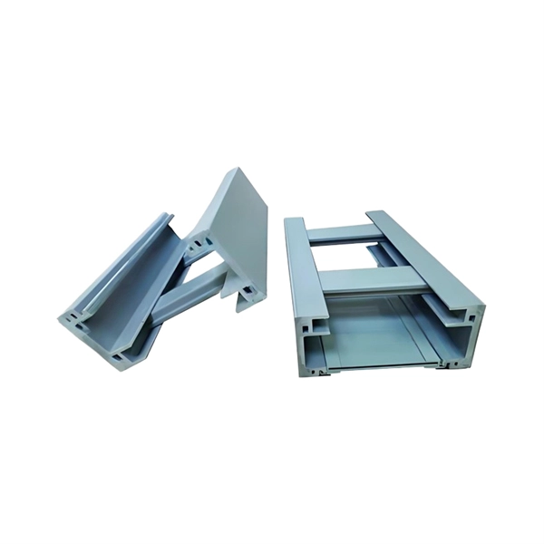
Explore all types of cable trays—ladder, perforated, basket, solid, and channel. Each cable tray type performs a different function and comes in various materials such as aluminum, galvanized steel, and FRP. What is Cable Tray? 1. Non-Metallic What is Cable. Cable tray systems are engineered support structures designed to route, support, and protect insulated electrical cables used for power distribution, control, instrumentation, and communication. Unlike conduit systems, cable trays allow cables to be laid in bundles, improving accessibility, heat. Below are the top 7 types of cable trays and their applications, along with their key advantages. Ladder Type Cable Tray The ladder type cable tray consists of two side rails connected by rungs, allowing excellent airflow around cables. Ladder cable tray is so named because it resembled a ladder. Ladder cable trays are relatively simple in. Selecting the correct cable tray for low voltage system—such as data networking, telecommunications, security, and building automation—is a critical decision that impacts system performance, scalability, and long-term reliability.
[PDF]
This guide covers everything: what fiber optic pigtails are, how they differ from patch cords, which connector and polish type to specify, how to choose between mechanical and fusion splicing, and the real-world applications where pigtails are the right call. Types and Applications A pigtail connector is a short cable with a connector on one end and bare (stripped) wire or fiber on the other. In fiber optics, pigtails are fusion-spliced to field fiber inside splice trays — the most common termination method in telecom and data center networks. In. Whether it's an electrical system in your car, home, or factory, the quality of the connection is essential, and that's where pigtail connectors come in. These small, often overlooked components ensure a strong, safe electrical connection. It serves as a bridge, allowing technicians to repair specific connection points without disturbing the rest of the system. By the end, you will have a comprehensive understanding of why pigtails deserve a place in every fiber deployment toolkit. People often make this connection in the field, where they must make temporary repairs or. Executive Summary: A fiber optic pigtail is one of the most commonly specified yet least understood components in structured cabling. Get the wrong connector type, the wrong polish, or skip proper fusion splicing technique—and you're looking at elevated signal loss, increased back reflection, and a.
[PDF]
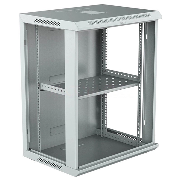
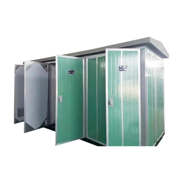
The BXM, BXD, and BXJ explosion-proof distribution boxes are engineered for the safe operation and control of specialized equipment in hazardous environments. Durable Hexlon Explosion Proof Distribution Boxes and Electrical Enclosures, IECEx and ATEX certified for Zone 1 and Zone 2. Order Explosion Proof Illumination Distribution Boxes from Warom Technology, a trusted manufacturer and supplier, designed for industrial lighting automation, hazardous electrical systems, nuclear illumination, defense applications, and waterproof, dustproof environments. ◆ The explosion-proof. It is widely used in flammable and explosive gas environment such as oil exploitation, refining, chemical industry, offshore oil platform, oil tanker, etc. Ideal for marine platforms, chemical tankers, LNG vessels, and dangerous cargo wharfs, these robust distribution boxes ensure reliable. Explosion Proof Box, SUREALL Low-voltage Control Guide Driving the state of the art innovation for power distribution and control for electrical equipment in harsh and hazardous location Explosion proof box, also called explosion proof boxes, include but not limit to explosion proof electrical. We supply certified explosion proof distribution box & Atex Transformer -Appleton, ATKON, CZ, CEAG, brands for safe and reliable industrial use.
[PDF]
This list includes both standards-based and real-world technical cable types utilized in fiber-optic infrastructure, telecoms, enterprise, and outdoor applications. • OFC: Optical fiber, conductive• OFN: Optical fiber, non-conductive• OFCG: Optical fiber, conductive, general use.
[PDF]
There are connectors designed for single mode and multimode fiber optic cables, which differ in core size, bandwidth, and optimal use cases as explained in this comprehensive guide to fiber optic cable.
[PDF]
One key aspect of this progression is the advent and evolution of transceivers, specifically SFP, SFP+, SFP28, QSFP+, and QSFP28. Let's delve into each of these technologies to understand their specifications, differences, and applications. A Cisco compatible SFP list 2026 represents a validated inventory of optical transceivers that utilize Multi-Source Agreement (MSA) standards to provide identical functionality to Cisco Original Brand (OB) optics. Deploying these modules allows network architects to reclaim up to 80% of their. —— Explosive Growth of 800G/1. 6T Technologies, Scene-Based Selection + Finisar Original Solutions in One Stop In 2026, driven by AI computing power, optical modules have entered a critical era of rate iteration, technological restructuring, and scenario segmentation. 800G has become the mainstream. Choosing the right Small Form-factor Pluggable (SFP) transceiver is critical for network engineers and procurement specialists aiming to optimize performance, cost, and reliability. This SFP buying guide offers a detailed technical comparison, real-world deployment insights, and practical selection. ity with compelling economics. Our ONE Network platform simplifies management of Cambium Networks' wired and wireless broadband and network edge technologies. Our customers can f iness rather than the network. We mak. SFP+ 10G ZR is designed for stable 80km single-mode transmission where standard 10G optics fail.
[PDF]
Basic run: 800 ft outdoor fiber drop with aerial installation, minimal trenching, and standard termination. Labor: 12–18 hours; Materials: $1,200; Total: $3,500-$6,000. Homeowners and businesses typically pay for fiber optic cable installation based on distance, conduit needs, and labor. The main cost drivers include material type, run length, trenching or aerial work, and any required permits or inspections. This article provides cost. A simple 1-core FTTH drop cable costs around $0. 13 per foot, while a 288-count optical fiber cable for building backbones can reach $6 per foot or more. Pre-terminated assemblies and patch cables incur higher costs due to factory termination, with prices varying by connector type and the number of. Whether you need singlemode, armored, or indoor plenum, this guide gives you the exact cost per foot of fiber optic cable — including installation — so you can budget without guesswork. Data aggregated from Q1 2026 contractor invoices across Texas, Ohio, and North Carolina. Understanding cost ranges helps buyers budget. Cost of Laying Fiber Optic Cable in the U. The price ranges reflect both ongoing improvements in fiber deployments and regional differences in permitting and crew rates.
[PDF]

This guide explains how to make 90° bends, vertical bends, tees, and offsets in wire mesh cable trays safely and professionally. Horizontal 90° Bend (Flat Bend) 2. Tee (T-Junction) Bend 4. Since the jaws of the bolt cutter drags a layer of zinc across the cut end and forms a protective layer. When a wire cable tray is cut, the fact that a. Wire mesh cable trays are widely used because of their flexibility and easy on-site modification. Unlike perforated trays, bends can be created directly at site without expensive fittings. Great if you are new or just forgot how to do it, this easy to follow guide makes it so simple. more The Easy Guide to. This involves a few essential steps to ensure a successful bending process. The first step in preparing the. The method for producing bridge bend elbows is as follows: Take a 90-degree cable tray bend elbow as an example, and apply the same principles for 45-degree bends accordingly. The length of the bottom side (bottom diagonal) after bending the cable tray should be equal to the width of the cable. OTHER THAN 90 ̊ JUNCTIONS Use this guide to learn the most effective installation practices when installing Cablofil tray. Each example of bends and tee's clearly illustrate proper tray cutting combined with recommended usage of Cablofil accessories. Engineers and contractors in North America and.
[PDF]
will introduce major upgrades to its Multi-Rail technology platform at ECOC 2025, targeting hyperscale optical transport with new efficiency, scale, and performance enhancements. Coherent Corp. SAXONBURG, PA, September 26, 2025 (GLOBE NEWSWIRE) – Coherent Corp. At the heart of the. SAXONBURG, Pa. At the heart of the. Simultaneously, coherent technology has emerged as the prevailing solution for Data Center Interconnection (DCI) applications, covering distances of 80~120km in the field of data communication. These evolving applications introduce new demands for coherent optical transceiver systems, steering the. Coherent optical module refers to a typically hot-pluggable coherent optical transceiver that uses coherent modulation (BPSK / QPSK / QAM) rather than amplitude modulation (RZ/ NRZ / PAM4) and is typically used in high-bandwidth data communications applications. Optical modules typically have an.
[PDF]