
However, essentially, optical fiber patch cords are more like "finished connection lines", while optical fiber pigtails are "semi-finished connectors". The difference in this core positioning determines the vast disparity between them in structure, connection methods. Executive Summary: A fiber optic pigtail is one of the most commonly specified yet least understood components in structured cabling. Get the wrong connector type, the wrong polish, or skip proper fusion splicing technique—and you're looking at elevated signal loss, increased back reflection, and a. When you build or upgrade a fiber network, the same four words pop up everywhere— fiber optic (bare fiber), pigtail, patch cord, optical cable. They're related, but they are not interchangeable. Mixing them up drives costs higher, increases loss, and slows your rollout. The good news? Once you nail. A fiber pigtail is typically a fiber optic cable with one end factory pre-terminated fiber connector and the other exposed fiber. It is usually suitable for field termination using a mechanical or fusion splicer. The connector end plugs into devices like transceivers or patch panels, while the bare end is typically fusion spliced to a fiber optic cable. This setup ensures. As outlined in T13: Fiber Optic Fundamentals, an optical fiber is a coaxial cylindrical dielectric waveguide with a core refractive index exceeding that of its cladding.
[PDF]

Learn how to splice fiber optic cable using fusion splicing with this complete step-by-step guide. Includes tools, best practices, loss standards (ITU-T G. 652), cost analysis, and FAQs for network engineers and installers. Splicing fiber optic cable is an extremely important phase for making dependable, high-speed communication infrastructures. Regardless of the type of fiber network you're deploying, be it for telecom, enterprise data centers, or smart city infrastructure, fusion splicing provides the benefits of. Proper connection of fiber optic cables is essential to harness these benefits fully, as even minor errors can lead to significant performance issues like signal loss. This article will guide you through the necessary tools, materials, and methods on how to connect fiber optic cables effectively. Previous video we explain how to do splicing of fibers optic cable in joint closure. this video are showing how to arrange sleeves in the cable tray and arrangement of fibers. Before connecting any fiber cable, you need to assemble the proper preparation tools: With the right tools in hand, follow these key steps to achieve reliable fiber connections: 1. Strip and Clean Fiber Ends. Fiber optic internet delivers blazing-fast speeds and reliable connectivity, making it a top choice for modern homes and businesses. However, setting up a fiber optic connection to your router can seem daunting if you're unfamiliar with the process.
[PDF]

This helps keep fiber optic cables safe from harm and signal problems when you put them in. Use the right lubricant. Follow the rules for tension and bend radius. Try new methods like air blowing. Use smart. Fiber optic cable is surprisingly strong, durable and pliable; however, several best practices should be followed to ensure a successful cable installation. This article explores recommendations for pulling and installing fiber optic cable. This makes sure the cable pull is smooth and safe. Use smart monitoring devices. The Future Ready Solutions Tools & Test. A duct is available from point A to point B, a pull tape is blown in, a fiber optic cable is attached to it and the cable is pulled through the duct. Sounds simple, doesn't it. Recent observations and conversations with more than a few people in the fiber optic business have indicated. Route plan to ensure the duct run maintains the minimum bend diameter of the cable. For more information and all recommendations for installation, refer to Corning Optical Communications Standard Recommended Procedure SRP 005-011, "Duct Installation of Fiber Optic Cable". more Route plan to ensure.
[PDF]

Here's a step-by-step guide to help you set up your fiber distribution box seamlessly: Before installing the fiber distribution box, ensure that your optical cables are properly prepared for connection. The optical fiber distribution box allows people to easily access the optical fibers in the box, and can well protect the optical fibers. In addition, the drawer structure also facilitates high-density wiring and good cable management. However, because optical fibers are fragile and can be easily. Keeping this page as a placeholder for now. Have any questions? Talk with us directly using LiveChat. Fix the rack to the ground with expansion bolts. Top installation: Dimensions of four connection holes on the top according to the. This instruction describes the installation of the Fiber Distribution Frame (FDF) manufactured by Corning Optical Communications. To order accessories that are purchased separately, contact Corning Optical Communications customer care for assistance. Read and understand this procedure (as well as. Optical fiber distribution frame is the wiring connection equipment between optical cable and optical communication equipment or between optical communication equipment. Distribution boxes are especially essential for FTTH networks, where they enable the efficient connection and management of optical fibers from a central.
[PDF]

Fiber optic cables use total internal reflection to keep light signals bouncing within the core, allowing data to travel quickly and with minimal loss. An optical fiber is comprised of a light-carrying core in the center, surrounded by a cladding that acts to traps light in the. Optical fibers are thin glass rods that use the properties of light reflection and refraction to transmit data over long distances. They actively shuttle data encoded in pulsing light across vast distances using only subtle differences in materials. They consist of three elements as shown in Figure 1: a central core, cladding and a protective coating. Optical fibers operate on the principle of total internal reflection, which. Refraction and total internal reflection (TIR) are the two fundamental optical principles that allow light to propagate through optical fibers over long distances with minimal loss. Understanding these mechanisms is essential for designing, installing, and troubleshooting fiber networks in FTTH. Fiber optic cables use a similar concept to guide light. Fiber optic. Describe the workings and uses of fiber optics. Analyze the reason for the sparkle of diamonds. A good-quality mirror may reflect more than 90% of the light that falls on it, absorbing the rest.
[PDF]

Typical rates range from $0. 00 per ft depending on terrain, access, and required precision for termination. Basic — 1,000 ft single-mode run indoors with minimal termination: Cable $0. 00/ft, Permits $150, Accessories $100. Total ≈ $2,650–$3,100. Fiber-optic cable materials typically cost $1 to $6 per linear foot, depending on fiber count and cable type. Commercial building installations with 100-200 network drops generally range from $15,000 to $30,000. Single-mode fiber costs less per foot than multimode fiber, but it requires more. Buyers typically pay for fiber optic cable by length, fiber type, and installation complexity. Main cost drivers include cable grade (indoor vs outdoor, armoured), distance, and labor for trenching, splicing, and termination. This guide presents ranges in USD and practical price estimates to help. The cost per foot of fiber optic cable is now the lowest it's been since 2021. Labor dominates the installed price. Here is the 2026 benchmark for cost of laying fiber optic cable per foot by method: Open trench (lawn/field): $0. 80 per ft – fastest, lowest cost. Directional boring (road. Single-mode fiber (OS2): This is the industry workhorse. In 2025, the base glass price has stabilized. You are looking at $0. The price swing usually depends on the fiber count (e., 12-core vs 96-core) and brand. This article breaks down the price landscape and provides.
[PDF]
Explore the top 10 fiber optic cable manufacturers in India known for premium quality, cutting-edge technology, and reliable network solutions. The Indian optical fiber cable market has experienced explosive growth, driven by ambitious government initiatives like Digital India, BharatNet, and the rapid 5G rollout. This comprehensive analysis examines the top domestic suppliers dominating this lucrative sector. The Indian optical fiber. This article will explore some of the leading fiber optic cable manufacturers in India, highlighting their contributions to the digital connectivity landscape. Aksh Optifibre Limited If you know about the fiber optic market in India, you most certainly know of Aksh Optifibre Limited. Why exactly. BIRLA CABLE LTD. Telecommunication Cables, which offers one of widest portfolio of Copper and Fibre Optic cables under its umbrella. P Birla Group Companies abide in taking Corporate responsibility very seriously. In keeping with all the statutory requirements of the. This report lists the top India Optic Fiber Cable And Accessories companies based on the 2023 & 2024 market share reports. Mordor Intelligence expert advisors conducted extensive research and identified these brands to be the leaders in the India Optic Fiber Cable And Accessories industry. Introducing you the details of India's top 10 fiber optic cable leading companies, unveiling their strengths, innovations, and effect. Aksh Optifibre Limited: 3.
[PDF]

Receiver sensitivity is the lowest optical power level at which an optical receiver can successfully decode data with acceptable bit error rates (BER). It's a core parameter in optical transceiver specifications, indicating the module's capability to detect weak incoming signals. The standards body governing the application sets this specified BER. For example, SONET specifies that the BER must be 10 -10 or better. What Is BER? The bit error rate (BER) measures the data transmission precision within. Receiver sensitivity stands as a critical parameter impacting an optical transceiver's functionality. It denotes a module's capability to function in challenging environments and aids network operators in determining the system's maximum reach or link margin. Lower receiver. Among a group of optical receivers, a receiver is said to be more sensitive if it achieves the same performance with less optical power incident on it. The performance criterion for digital receivers is governed by the bit-error rate (BER), defined as the probability of incorrect identification of.
[PDF]
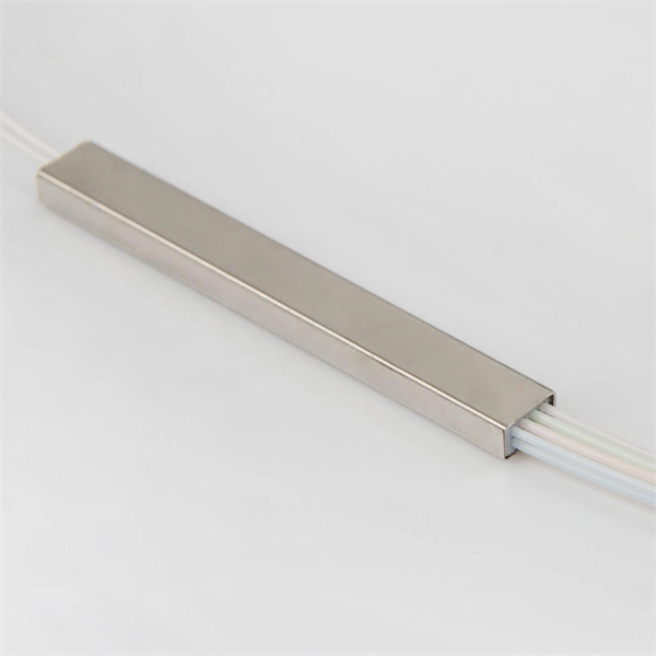
Shop cable conduit and interduct for fiber and network cable protection. Ideal for both indoor/outdoor use, this product is easy to install. 1" PVDF Plenum Rated Fiber Innerduct Snap Coupling (for F1-11437 and F1-11437S only). Corrugated, smooth or split wall types. Fiber cable tray/duct is designed to protect and route fiber optic patch cords, multi-fiber cable assemblies, and intrafacility fiber cables (IFC) to and from fiber splice enclosures, fiber distribution frames and fiber optic terminal devices. Our fiber duct/tray is manufacturder with fire. Innerduct is used to protect fiber optic cables as they are routed through buildings or underground. Inner duct product line consists of corrugated HDPE, riser rated PVC and plenum rated PVDF. UL 2024 listed and among the most flexible flame-rated Inner duct products on the market. These ducts are essential for maintaining signal integrity, preventing physical damage, and ensuring long-term reliability in various environments. PVC innerduct conduit is non-metallic, lightweight, corrugated, and flexible to protect and route electrical wire and cables. Note: Product availability. 1-1/4" Diameter, Corrugated HDPE (High Density Polythylene) Innerduct, Orange. Includes: Pull String. No UV Protection, not suitable for outdoor use. Category: Corrugated.
[PDF]

Fiber optic loss calculation formula: Total link loss (LL) = Cable attenuation + Connector attenuation + Fusion attenuation [Note: If there are other components (such as attenuators), their attenuation values can be added]. Intrinsic Optical Fiber Losses comprise of absorption loss, dispersion loss and scattering loss caused by the structural defects. The detailed information about these optical losses and how to reduce them are. Calculate fiber optic signal loss based on cable length, attenuation, and connector losses. Determine cable loss, connector loss, and total system loss in decibels (dB) to assess signal quality and repeater requirements. Fiber optic loss is calculated in two parts: cable loss and connector loss. This calculator determines fiber loss based on input power, output power, and the length of the fiber optic cable. In summary, fiber optic loss is. Use this worksheet to input values for all variables that will impact your system's performance. After entering your values, please ensure you click the 'Calculate Link Loss' button at the bottom of the page to generate your total link loss. This step is necessary to see if your system falls within. Optical fiber loss is a term for signal loss affecting transmission reliability. Optical fiber loss is.
[PDF]

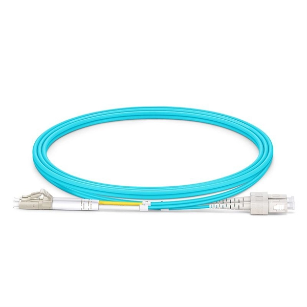
Since the earliest days of fiber optics, multimode cables have typically been color‑coded orange, black, or gray, while single‑mode cables are marked in yellow. For example, cable jacket color typically defines the fiber type, and can differ based on mode and performance level. These colors are typically chosen by industry standards bodies. However, there are some non-standardized colors and inconsistencies that you should be aware of. However, with the introduction of metallic connectors like FC and ST—whose bodies are difficult to color‑code—colored strain relief boots. Multimode fiber (MMF) is a kind of optical fiber mostly used in communication over short distances, for example, inside a building or for the campus. Multimode fiber optic cable has a larger core, typically 50 or 62. 5 microns that enables multiple light modes to be propagated. Because of this, more. Originally developed by the Electronic Industries Alliance (EIA) and the Telecommunications Industry Association (TIA), the TIA-598-D standard (formerly EIA/TIA-598) remains the most recognized color-coding system for optical fibers worldwide. On the right, the yellow patchcord indicates singlemode fiber and the blue connector means it is a regular PC polished connector, If it were an APC connector, it would be green. Perhaps nothing is.
[PDF]

Contrary to popular belief, fiber optic cables do not contain copper. Instead, they consist primarily of glass or plastic fibers that transmit data using light signals. These fibers are surrounded by protective coatings made of materials such as polymer or epoxy resin. Fiber optic cables are designed to provide high-speed, no-signal-loss, and EMI-free communication in telecommunication, powergrid, datacenter, broadband, and industrial applications. Each optical cable is constructed using a precise combination of optical fibers, strength members, buffer tubes. Fiber optic cables use pulses of light through ultra-pure glass or plastic fibers to carry information rather than electrical signals. Cladding: Lower refractive index layer reflecting light back into. You might wonder if there's copper inside fiber optic cables. It's not a yes-or-no answer. So, it's about knowing the different types. Its primary method of data transmission relies on light signals traveling through glass or plastic fibers, rendering copper conductors unnecessary for that purpose. Fiber optic cables have revolutionized data transmission. The two core material technologies used in almost all cables are fiber optic, and copper wiring.
[PDF]

The fusion method fuses the fiber cores together with less attenuation. Fusion splicing stands out as a superior technique for joining optical fibers, offering a seamless, low-loss connection that is crucial for reliable fiber optic networks. Thorlabs offers a varied selection of single mode (SM), polarization-maintaining (PM), multimode (MM), and double-clad fiber couplers, as well as 1x8 and 1x16 SM PLC splitters; 1x4, 1x8, and 1x16 PM PLC splitters; wideband multimode circulators; RGB combiners; and WDMs. Our SM and double-clad fiber. Castor's Multimode Fiber Splitters (MFS) are designed to efficiently split or combine multimode signals with minimal insertion loss. Manufactured with step-index fibers with core diameter ranging from 50 to 400 µm, they offer uniform splitting ratios across output channels. This method provides a simple, rugged, and compact method of splitting and combining optical signals. Let's explore the fundamentals of mechanical and fusion. A fiber optical coupler (splitter/combiner) route signals to their appropriate destination by splitting, combining or tapping optical signals/channels in a fiber transmission link. Employing a unique fiber fusing process, Lfiber is now able to fabricate and offer a wide variety of fiber optic. Fused couplers are ideal components to split or combine light signals between two fibers over a wide wavelength and temperature range.
[PDF]

The basic structure of optical fiber consists of three primary components: the core, the cladding, and the buffer coating. The core is the central part of the optical fiber through which light is transmitted. An optical fiber cable is a complex structure designed to protect fragile glass fibers that transmit digital data using light signals. This advanced cabling solution allows fast, secure data transfer and telecom over long distances. Understanding the components within a fiber optic cable enables. In this blog, we will delve into the fundamental components and structure of optical fiber to gain a better understanding of this revolutionary technology. At its core, optical fiber is a thin, flexible, and transparent fiber made of glass or plastic, which serves as a medium for transmitting light. They consist of three main components and are available in several structures suited to different uses. In this article, discover in detail these components and the various structures of fiber optic cables. The core: made of silica, molten quartz, or plastic, in which optical waves propagate. Dielectric material conducts.
[PDF]

While most pigtails are single-fiber, multi-fiber options exist: Single-fiber: The most common (LC, SC, FC). Multi-fiber: 2, 4, 6, 12, 24, 48, or 72 fibers. Multi-fiber pigtails often come in ribbon format for splicing into high-count cables. Traditional Fusion Splice-On Connectors with pigtails provide factory-polished performance with field-termination convenience within harsh environments. Mass fusion splicing can fuse up to all 12 fibers in one ribbon at once. Mass Fusion Pigtails come with all 12 fibers terminated and a ribbonized. By fiber type, there are single-mode fiber optic pigtail and multimode fiber optic pigtail. And by fiber count, 6 fibers, 12 fibers optic pigtails can be found in the market. Fiber pigtails are used in an estimated 99% of single-mode fiber applications worldwide. Despite this ubiquity, they remain a source of confusion for procurement teams and junior installers alike—especially when it comes to connector type selection, polish type, and the tradeoffs between mechanical. Fiber optic pigtails can be divided into single-mode and multimode fibers. Conversely, multimode fiber pigtails, usually orange, use a 62. 5m to 2m—that has a factory-terminated connector on one end and bare fiber on the other end. The connector end is polished and tested under factory conditions, ensuring low insertion loss and high return loss.
[PDF]