A fiber-optic splitter, also known as a beam splitter, is based on a quartz substrate of an integrated waveguide optical power distribution device, similar to a coaxial cable transmission system. The optical network system uses an optical signal coupled to the branch distribution. The fiber optic. These unassuming devices enable a single optical signal to be divided into multiple paths, making them indispensable for sharing network resources efficiently—from residential FTTH (Fiber-to-the-Home) connections to large-scale telecom backbones. Optical splitter. Fiber optic splitter is a passive optical device used to distribute optical signals, which can divide input optical signals into multiple outputs to meet the fiber optic access needs of multiple terminal devices. Optical splitters are a very important component in fiber optic links, widely used in. They are devices that split an incident light beam into several light beams at certain splitting ratios. The role of these splitters in optical networks is crucial as they allow a single optical signal to be shared among many users, thereby enhancing the efficiency and capacity of the network. Each type serves specific applications, enabling efficient use of optical infrastructure.
[PDF]
A fiber-optic splitter, also known as a, is based on a of an integrated waveguide power distribution device, similar to a The system uses an optical signal coupled to the branch distribution. The splitter is one of the most important in the link. It is an optical fiber tandem device with many input and output terminals, especially applicable to a passive optical network (,,,.
[PDF]

The box is typically composed of several parts, including the enclosure, the splitter module, and the connectors. An optical cable split fiber box is a device used in fiber optic communication networks to split the signal from one input into multiple outputs, allowing multiple devices to be connected to a single fiber optic cable. This provides users with a dependable and high-speed network service and little to no wait times. There is no need for an FDB if there is no. In modern FTTH (Fiber to the Home) and optical communication networks, three types of fiber distribution products are widely used: Splitter Distribution Box, ODF (Optical Distribution Frame), and Fiber Terminal Box. Although they all belong to the optical distribution and management system, their. A fiber optic splitter is a passive optical component that divides a single incoming optical signal into two or more outgoing signals, or combines multiple incoming signals into one. It can divide the input optical signal into multiple output optical signals to meet the fiber optic access needs of multiple terminal devices. This type of device plays an important role in passive. In this kind of fiber cabinet, the backbone fiber optic cable usually does not connect to optical splitters. However, in some metropolitan area, the backbone fiber cable will.
[PDF]
A fiber-optic splitter, also known as a, is based on a of an integrated waveguide power distribution device, similar to a The system uses an optical signal coupled to the branch distribution. The splitter is one of the most important in the link. It is an optical fiber tandem device with many input and output terminals, especially applicable to a passive optical network (,,,.
[PDF]

The max insertion loss of a fiber patch cable is 0. 75 dB (the maximum acceptable value) in the TIA standard. Insertion loss (IL) and return loss (RL) are key performance indicators of fiber optic patch cords. This article explains their concepts, standards, testing methods, and FiberMania's quality assurance workflow to ensure optimal network performance. Fiber optic patch cords are crucial components in. A: Fiber optic loss refers to the reduction in signal strength as it travels through the fiber optic cable. This can be due to various factors, including attenuation, connectors, and splices. Q: How is fiber optic loss measured? A: Fiber optic loss is typically measured using an Optical Loss Test. The estimate, called a "loss budget" is calculated using typical component losses for each part of the cable plant - the fiber, splices and/or connectors. If the measured loss exceed the calculated loss by a significant amount (remembering the inherent uncertainty in all measurements), the system. Insertion loss is usually shortened to IL, and the unit of measurement for insertion loss is dBm. ) in transmission systems. It is the power attenuation of the signal after. At TARLUZ, we specialize in manufacturing high-performance fiber optic patch cords that comply with global industry standards, ensuring optimal signal integrity and long-term stability.
[PDF]

In this tutorial, we will show you how to fusion splice two fiber optic strands together in an easy 12 step process. The answer lies in splicing, both fusion and mechanical. Whether you're a professional technician or a DIY enthusiast, understanding the process of fusion splicing fiber optic cables is essential for maintaining high-speed communication networks. - Fiber Instrument Sales What is Fusion Splicing? How fiber optic splicers work, types, what they are used for. Steps to use this equipment and including how to test your fiber splice. The guide covers everything from basic principles of fusion splicing to detailed procedures; it is intended to provide both newbies and professionals with the necessary knowledge and skills. The operation and skills of fiber optic fusion splicing technology can be mainly divided into five steps: fiber stripping, fiber cutting, fiber melting, fiber sleeve, and fiber winding. And tools used for fiber fusion: fusion splicer; fiber cleaver; cable stripper; fiber optic stripper; alcohol;.
[PDF]
The securing, storing and supporting of fiber optics and splices makes up an important step of fiber optic deployments in the field. Whether connecting to aerial or underground cables, telecommunication.
[PDF]
Learn how to install a fiber optic termination box step-by-step for FTTH projects. Covers mounting, splicing, routing, labeling, and testing for indoor/outdoor use. Installing a fiber optic termination box is one of those jobs that looks simple on paper, but it's. In the realm of optical communication networks, the optical splitter serves a vital role in dividing and distributing optical signals efficiently. Understanding how to properly place and use an optical splitter is essential for optimizing signal quality and ensuring seamless data transmission. WvW Fiber and networking solution. In this video, I walk you through my personal method of prepping and installing a 1:16 fiber optic splitter inside a sealed, weatherproof distribution box getting it ready for field deployment at a site. This is the way I've found to be clean, efficient, and. A fiber optic splitter box is a device used in fiber optic networks to split a single optical signal into multiple signals, allowing for the distribution of data to multiple endpoints. The splitter box contains a splitter, which is a passive optical device that divides the incoming light signal. You use optical couplers and splitters to split or join signals in fiber networks. These devices help you control light signals well. For example, optical splitters send light to many output ports. Have any questions? Talk with us directly using LiveChat.
[PDF]

FiberMall MPO16 APC Y Splitter Cables 10m are designed for 800G QSFP-DD/OSFP DR8/OSFP XDR8 optics direct connection and support 800G transmission for Hyperscale Data Centers. Multimode PLC Splitter is a passive optical device used to split incoming signals into two or more output signals. They're capable of operating over a broad wavelength range from 650 nm to 1350 nm (Typ. 650nm, 850nm and 1300/1310nm). 5/125 (OM1, OM2, OM3 and. High-Quality Construction: This Fiber Optic PLC Splitter is manufactured by UT-KING, a reputable brand known for its reliable products, ensuring a durable and long-lasting performance. Optimized for FTTH Solutions: Designed for use in Fiber-to-the-Home (FTTH) applications, this 1x2 OM3 PLC Splitter. Optical coupler is an optical device that combines or splits power from optical fibers. Note: All insertion loss and insertion loss referenced without connectors. Takfly, established in 2000, has been manufacturing. Optional split ration 1:99, 2:98, 5:95, 10:90, 20:80. USource OM3 Fiber Coupler is a 1x2 or 1x3 passvie optical multimode splitter based on FBT (Fused Biconic Taper) technology, packaged in mini ABS box module or steel tube, split into different rations 1:99, 2:98, 50:50, 10:90, 20:80.
[PDF]
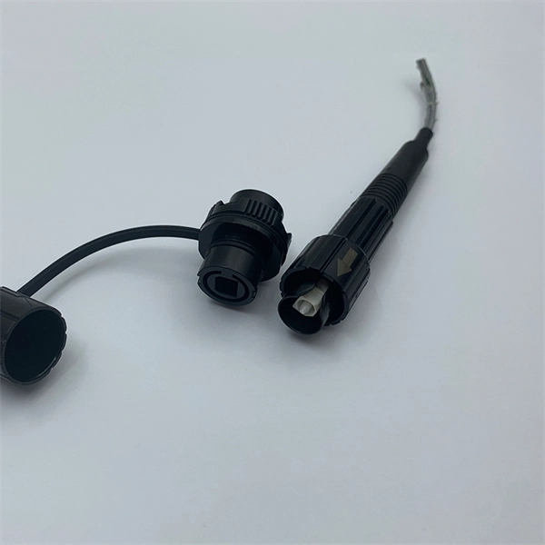
A distribution box serves as a central point for managing and distributing fiber optic cables. This device ensures reliable and efficient connectivity between various network components. By combining factory-installed connectors with spliced bare fiber, pigtails ensure that network installers can create fast, reliable, and cost-effective terminations. Without pigtails. A fiber pigtail is a type of fiber optic cable with a factory pre-terminated connector on one end and exposed fiber on the other. This design makes the fiber pigtail suitable for field termination using a mechanical or fusion splicer, playing a crucial role in the fiber optic cable installation. A Fiber Optic Termination Box is a small enclosure located at the terminal end of the fiber where it enters your customer premises. Its function is primarily to splice, secure, and protect the optical fibers connecting the incoming drop cable to the pigtail or patch cable. The connector end plugs into devices like transceivers or patch panels, while the bare end is typically fusion spliced to a fiber optic cable. You can splice the bare end with a fiber core of an optical cable, thus providing a connection for the fiber.
[PDF]

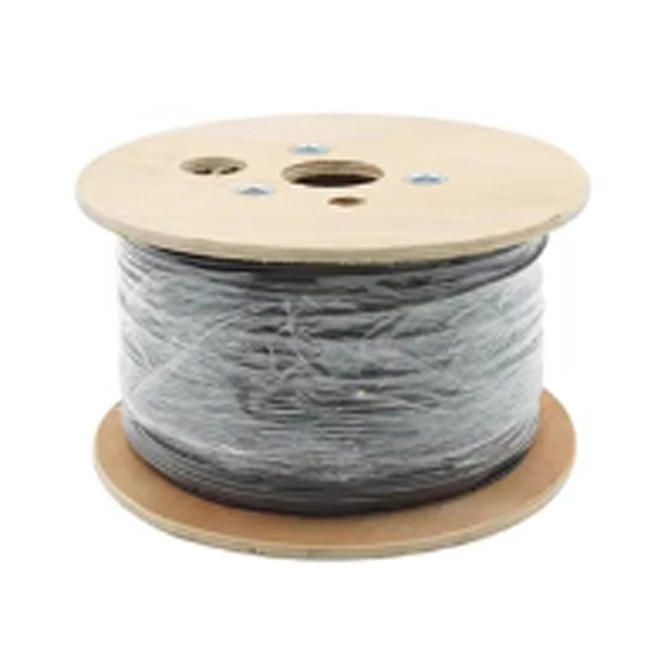
This article provides a detailed technical comparison between fiber optic and copper cables, offering a clear perspective for engineers, network architects, and procurement managers. The core distinction between the two technologies lies in the physics of data. There are significant differences in performance between ADSS cables (all-dielectric self-supporting optical cables) and traditional optical cables, which are mainly reflected in the following aspects: 1. This type of fiber optic cable is designed to support its own weight without the need for additional support structures like messenger wires. The ADSS. There are several factors to assess when deciding which cable type is right for your application, including speed of connection for new customers, ease of changes and repairs, installer certification requirements, and the ability to expand the network over time. ADSS Fiber Optic Cables are a type of optical fiber cable designed specifically for. All-dielectric self-supporting (ADSS) cable is a type of optical fiber cable that is strong enough to support itself between structures without using conductive metal elements. It is used by electrical utility companies as a communications medium, installed along existing overhead transmission.
[PDF]

A8: Yes, multimode fiber optic cable can support high-speed data transmission depending on the fiber type and network equipment used. Multimode fiber (MMF) is an optical fiber designed to carry multiple light propagation paths—or modes—simultaneously. This is made possible by its relatively large core diameter, typically 50 or 62. 5 microns, compared to the ~9-micron core in single-mode fiber. The wider core accepts light from. Multi-mode optical fiber is a type of optical fiber mostly used for communication over short distances, such as within a building or on a campus. Multi-mode links can be used for data rates up to 800 Gbit/s. Multi-mode fiber has a fairly large core diameter that enables multiple light modes to be. In the realm of telecommunications and networking, multimode fiber optic cable plays a crucial role in efficiently transmitting data over short to medium distances. This guide aims to provide a concise understanding of multimode fiber optic cable and its applications. These fiber cables are structurally designed to transmit several light signals simultaneously, each of which is directed. Unlike copper cables, which rely on electrical signals, fiber optics use pulses of light to transmit data—offering unmatched bandwidth, low interference, and long-distance capabilities. But not all fiber cables are created equal: multimode (MM) and single mode (SM) fibers are the two primary types.
[PDF]
In conclusion, choosing the right fiber optic connectors is an important decision that can have a significant impact on the performance and reliability of your fiber optic network. By considering the various factors.
[PDF]

Configurations of 1x1 to n x m (e., 1x8 or 2x2) are available. The insertion loss of MM switches typically amounts to approximately 0. These switches can be delivered with any of the. Multimode fiber optic switches have emerged as a crucial component, enabling seamless connectivity and efficient data transmission. The MCSW Series Multicast Fiber Optical Switches enable simultaneous connection of one input to all outputs without loss. They support fully non-blocking, conflict-free switching of any number of optical inputs to any outputs, with complete configuration flexibility. The system is entirely passive. The Siemens Scalance X204-2 Multimode Switch requires a 24V UL Listed for Fire Application, Power Limited - Regulated Power Supply. Its Input Voltage is Regulated 24VDC and its Input Current is 265mA @ 24VDC. It is powered from the battery backed up local 24V power supply. Was this helpful? Does. For extremely precise measurement systems and sensor applications as well as for telecommunication applications LASER COMPONENTS offers fiber optical multimode (MM) switches with a fiber core diameter of 50 µm to 600 µm. There are switches are for all different kinds of requirements. Configurations. CONFIGURING THE SWITCH IN DESIGO CC/CERBERUS DMS. CYBERSECURITY DISCLAIMER.
[PDF]

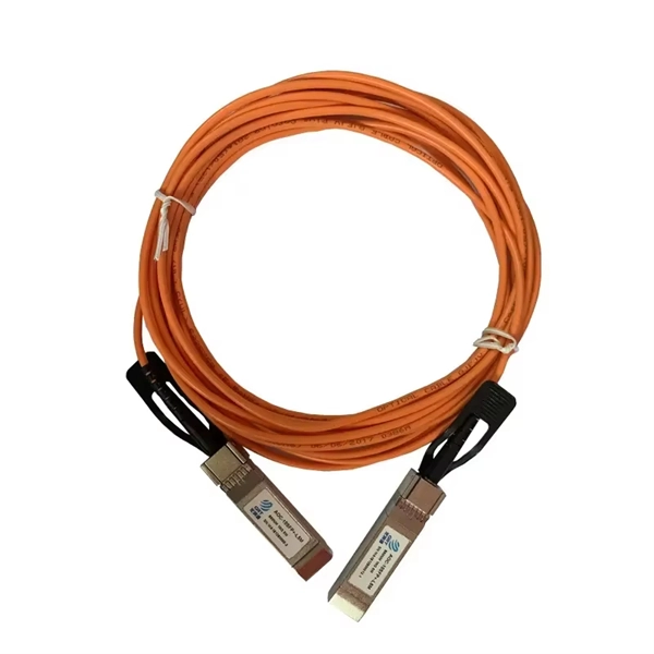
Plug an SEL-2810 Fiber-Optic Transceiver With IRIG-B directly into a standard 9-pin serial connector (DB-9). No special mounting is required. The SEL-2810 receives power from the host device via the connector; no separate power supply or power wiring is needed. It also requires no. Improve safety, signal integrity, and reliability by using optical fiber instead of wire for instrumentation, protection, automation and other applications that benefit from economical fiber-optic links up to ½ kilometer long. Fiber-Optic Link— Establish EIA-232 communication between devices over a. The RLH Contact Closure Fiber optic converter transmits 8 digital input signals over fiber optic cable. Applications include alarm event triggering, building automation, environmental control systems, fire & alarm systems, gate control, traffic signal control equipment, and more. Use two optical fibers instead of 32 wires between outdoor or remote equipment and the control building to reduce costs, improve safety, and boost reliability. SFP transceivers bridge electrical and optical signals, making them indispensable in data centers, telecom networks, and.
[PDF]