Pilot-wire relaying is an adaptation of the principle of differential relaying to line protection and functions to provide high-speed clearing of the line for faults anywhere on the line. Pilots include wire pilot (us.
[PDF]
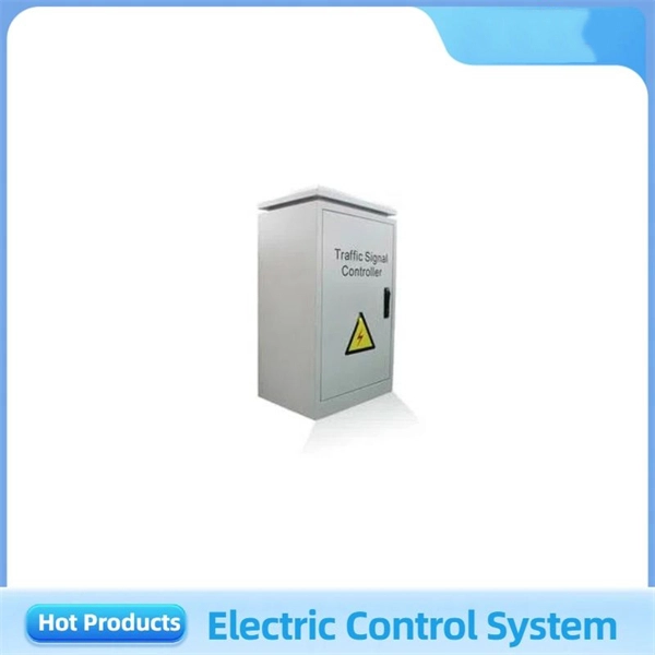
At Multilink, we offer traffic power solutions to keep traffic signals, camera equipment, illuminated street signs and other tech up and running. Power traffic signals, camera equipment, lighting and other t.
[PDF]
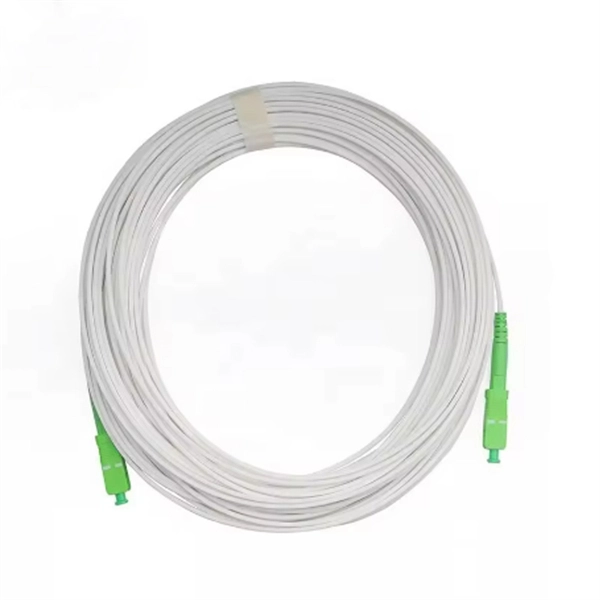
Too many connections can cause too much signal loss. Clean your connections. As we discussed above, remove dirt, dust and oil from fingerprints with pen-style cleaners or alcohol wipes. Identify cable damage using a VFL tester. If identified, re-splice the cable. When issues like signal loss, slow speeds, or intermittent connectivity arise, systematic troubleshooting is key. This guide will walk you through diagnosing and resolving common fiber network issues efficiently. Why Do Fiber Networks Fail? Despite their robustness, fiber networks can fail due to:. Problems with fiber optic internet can range from signal attenuation to optic signal loss to equipment malfunctions. By shedding light on these common fiber internet problems and offering insights into preventative measures and advanced troubleshooting steps, we aim to empower network. Fiber optic troubleshooting is an essential skill for network administrators, technicians, and engineers responsible for maintaining and repairing fiber optic systems. These high-speed, high-capacity communication networks are increasingly replacing copper cables, offering superior performance and. Clean Fiber Optic connectors often to stop dirt and dust. Finding problems early saves money. It also stops long network downtime. Use the right tools to test for weak spots. These networks are the backbone of modern data transmission, offering incredible speeds and bandwidth.
[PDF]
It is not recommended to place your router inside a cabinet as it can lead to poor Wi-Fi signal strength and potential overheating issues. Cabinets typically have materials that can interfere with the Wi-Fi signal, resulting in reduced coverage and slower internet speeds. For optimal performance. 💧 Water absorbs WiFi signal. Large aquariums or other significant water sources near your router can cause real connectivity issues, since water molecules are particularly effective at absorbing radio wave energy. 🏠 Router placement is your single most controllable variable. Careful planning ensures your router stays cool and your internet connection remains. Whether you're using a single Wi-Fi router or a mesh network, positioning your hardware correctly can make a major difference in speed, reliability, and coverage. Hiding your router in a cabinet or tucking it behind your TV might look tidy, but it's probably weakening your signal. After years of. In our increasingly connected world, a strong Wi-Fi signal is essential for everything from remote work to streaming entertainment. Yet many homeowners unknowingly place items near their routers that can significantly weaken their internet connection. Understanding what objects interfere with your. Positioning your router behind large furniture, under shelving units, or enclosed within cabinets can substantially degrade its performance.
[PDF]

If the LOS light on your fiber router or ONT is blinking red, it usually means Loss Of Signal. This guide explains the likely causes, the checks you can do at home, and when the issue needs technician support. The LOS light on your router indicates the status of your internet connection to the Internet Service Provider (ISP). When it's green and steady, everything is fine. However, when it blinks red or stays solid red, it signifies a Loss of Signal, a problem preventing your router from communicating. A red light on your router can be a source of frustration and confusion. Fortunately, diagnosing and resolving these issues doesn't have to be complicated. Before you panic or call tech support, there are several simple fixes you can try at home that often solve this problem in minutes. Here are some steps you can take. You might feel like you're staring into the abyss of digital darkness, wondering what went wrong. But don't despair! This guide will walk you through the most common causes of router.
[PDF]
Optical amplifiers work differently. They amplify the light directly, with no conversions. This process is faster, more efficient, and keeps the signal clearer. Using optical amplifiers helps reduce signal distortion, lowers system costs, and supports long-distance communication. The most common types include: Erbium Doped Fiber Amplifiers (EDFA): EDFAs are the most commonly used type of optical amplifier in telecommunications. They play a vital role in modern optical communication systems, enabling the transmission of high-speed data over long-haul networks. An optical amplifier is a device that boosts the strength of an optical signal. 2dB per kilometer for 1. This means that over a distance of 100km, a signal can lose around 20dB. This principle dictates that a photon can interact with an atom already in an excited energy state, forcing the excited atom to immediately release its stored energy as a second photon. It does this without changing the light into an electrical signal. In the past, systems used repeaters to fix weak signals. These repeaters turned light into electricity, boosted the signal, and then. The SPIE Digital Library offers a comprehensive range of content on optical amplifiers, reflecting their significance in modern photonics and telecommunications. The library includes a variety of peer-reviewed papers, conference proceedings, and technical articles that delve into the fundamental.
[PDF]

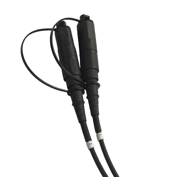
Though the equipment using the fiber may have noisy fans that you could hear. Fiber optics do not emit any audible sound under normal operation. Fiber optic splicing is a foundational process that directly dictates the performance and reliability of data transmission. Two primary methods exist:. Fusion Splicing: This advanced technique uses an. The performance of a fiber optic splice is determined by a number of factors, including the quality of the fiber, the cleanliness of the splice, and the techniques used to make the splice. Intrinsic factors, such as the refractive index of the fiber, are those that are inherent to the fiber itself. Tech coming out on Sunday but my question is how does the fiber optic effect the tv service if it does at all? I've noticed lately how my cable signal has some noise and blurriness. Tech coming out on Sunday. The physics of noise in optical communication links is of great interest in the design of fiber optic communication systems. This can occur due to a number of factors, including excessive bending, crushing, or twisting of the cable. Damage to the cable can cause signal loss, poor performance, or even complete failure of the. With its greater bandwidth capacity and ability to transmit signals over long distances with very little power loss, fiber has become the hands-down favorite for the future of Broadband. Fiber's resistance to magnetic interference makes transmissions nearly noise free, and it has the advantage of.
[PDF]
5 inch CETC Optic fiber OTDR AV6418,Fiber optic test tester,1310/1550nm,45/43dB large dynamic range,built in Optic power meter and VFL Description: AV6418 OTDR mainly used to measure the physical characteristics of optical fiber under test,such as the length,the transmission loss. 6. 5-inch display offers an event blind zone of 1 m and operates with locater This product is already in your quote request list. Measuring Measuring loss (dB) in the range between 800nm – 1700nm. Power AC/DC adapter; Input:100V~240V, 50/60Hz. Polarization extinction ratio (PER) is a measure of the degree to which light is confined in a principal linear polarization mode. It is defined as the ratio of the power in the principal polarization mode to the power in the orthogonal polarization mode after propagation through a device or. The ERM2xx Extinction Ratio Meters measure the polarization extinction ratio (PER) and the polarization angle of polarization-maintaining (PM) fibers. It features unmatched low cost, all wavelength options, a large dynamic range, and high resolution. The design adds a rotary polarizer to an optical power meter.
[PDF]
Find top-rated polarization extinction ratio meters with >40dB performance, real-time measurement, and USB output. Compare verified suppliers, pricing, and specs. Click to discover reliable options for lab and field use. The ERM2xx Extinction Ratio Meters measure the polarization extinction ratio (PER) and the polarization angle of polarization-maintaining (PM) fibers. These easy-to-use benchtop devices are useful in alignment applications such as connectorization of PM fibers or pigtailing of laser diodes with PM. This is the CUBE-ER100 and CUBE-PM100 Duo for automated high dynamic PER measurement (>46dB) CUBE-PM100 converts the polarization of the input broadband light to linear polarization through a higher PER (>50dB) polarizer. It then couples the linearly polarized light into the PM fiber under test. A polarizer is rotated in front of a high-speed power meter. The ERM-202 is a rotating-polarizer polarization extinction ratio meter. It is available in single or dual channel versions. The ERM-202 combines low noise circuitry with a high resolution stepper motor to achieve a PER dynamic range of 50 dB and angle resolution of 0. It simultaneously. OZ Optics Online. Please check your network connection and try again.
[PDF]
The noise performance of an erbium-doped fiber amplifier (EDFA) is characterized by modeling optical amplifiers as four-level or three-level systems. The gain and noise performance are then examined under forward and reverse pumping. A polynomial regression model using Generalized Least Squares (GLS) is proposed for real-time noise figure estimation in Erbium-Doped Fiber Amplifiers (EDFAs), achieving accuracy within the measurement uncertainty of optical spectrum analyzers. In this paper, a simulation of an EDFA has been studied to. Noise characteristics of erbium-doped fiber amplifier pumped at 980 nm. 4dB was measured for pump powers of on y 5. 8mw, cons multiplexed video transmission systems4 operating in the 1. This content is available for download via your institution's subscription. To access this. paper and electronic copies of this thesis and grant others the right to do o. Figure 1: Layout of the system considered in the analysis of gain and ASE The characteristics of noise and gain.
[PDF]

A slight breaker box humming noise from your electrical panel is highly normal and should not be of concern to you. To explain, what you're mainly hearing is the flow of electrical current within the circuitry of your home. There are plenty of reasons why you hear that electrical box humming noise. For easier reading, I have listed the reasons why your circuit breaker buzzes when turned on. The causes are organized according to their severity. Faint Circuit Breaker Buzzing Now, faint, distinct buzzing emanating. What Causes Buzzing Sounds in Your Electrical Panels? Hearing buzzing sounds in your electrical panel? Learn what causes it, when it is dangerous, & how The Electricians can help keep your home safe. Some common reasons for electrical humming or buzzing noises include: If electrical wires are not properly secured or damaged, they can vibrate and emit a humming noise. This could be due to natural wear and tear, poor installation, or animals chewing on exposed wiring. While a faint, steady hum from a transformer or large appliance is sometimes a normal byproduct of electrical flow, loud or irregular noises often signal an. Your electrical panel making noise can be disconcerting because these sounds typically indicate underlying issues you must address promptly. Even while you shouldn't be overly concerned when you hear this sound, there are some cases in which it could indicate that there is a major issue with the electrical system in.
[PDF]

