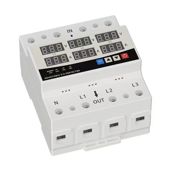
Step-by-step guidance on installing an electric meter box safely—site prep, clearances, mounting height, wiring, grounding, permits, and code compliance explained. 11 When Should You Hire a Licensed Electrician for Meter Box Installation? What Is an Electric Meter Box and What Does It Do? An electric meter box (often called a meter enclosure or meter socket) is the enclosure that holds the meter socket and supports the utility meter that measures energy use. Learn safety tips, wiring steps, troubleshooting, and when to call a pro. An electric meter box measures how much electricity your home uses. It helps the utility company give you the right bill. If you're setting up a new one or replacing an. In this guide, we will break down the key elements involved in connecting the main power supply to your home, providing a clear path for a successful setup. We will focus on the critical parts of the system, from basic components to step-by-step assembly procedures. Installing an electric meter box might seem like a job for professionals only—but with the right knowledge, it's a task many homeowners. Limited the meter location from pad mount transformer for PSO. Removed unistrut being listed as an alternative means for mounting the meter box. APCo and TX do not allow unistrut for installations. 7/2020 Revised Figure 15. Added wording for consistency with Section 8 of document.
[PDF]

Product Features: Square protective box, suitable for skin cable and leather cable tight protection 6cm in length of skin heat shrink tube welding protection. A close connection between the leather cable and pigtail. Looking for specific info?. *In the era of high bandwidth, reliable fiber optic power equipment is particularly important. This handheld photometer can help check cable performance, calculate relative power loss, locate faults, and troubleshoot. *Measure the length of network cables, coaxial cables, and telephone cables. Able. Usually ships within 3 to 4 weeks Click here for details of availability. Able to test open, short, cross-connect, See more product details TABKER 4000667180167 3 x 2 x 1. Check each product page for other buying options. Price and other details may vary based on product size and color. Need help?. power across any given fiber. This document will serve as an overview of the major features and functions of the device and will ofer tips for trouble shooting com on issues in optical networks. If you are looking for a low cost device capable of saving and reporting take a look at the RP460 or. ments to the instrument's performance and functionality. The figures given in this manual ion of this manual to ensure the accuracy of its contents. However, should you have any questions or fi gistered users with a variety of information and services. Please allow us to serve you best by.
[PDF]

Recommendation ITU-T L. 12 specifies splices of single-mode and multimode optical fibres. It describes suitable procedures for splicing that should be carefully followed in order to obtain reliable splices between single optical fibres or ribbons. Typical applications of these methods include aerial, buried, and underground splices. (2) American National Standard Institute/National Fire Protection Association (ANSI/NFPA) 70, 1993. § 1755. 370 - RUS specification for seven wire galvanized steel strand. 400 - RUS standard for. ation or liability to users of this publication. Existence of a standard shall not preclude any member or nonmember of NECA or FOA from specifying or using alternate construc Code (NEC) in effect at the time of publication. Because they are quality standards, NEIS® may in some instanc s go beyond. RUS standard for splicing copper and fiber optic cables. (FOA) was founded in 1995 to help develop the workforce to build the fiber optic networks to support a rapid expansion in communications and the Internet. The charter of the FOA was to promote professionalism in fiber optics through education, certification, and.
[PDF]
OPGW cable vibration dampers are essential devices designed to reduce aeolian vibration in optical ground wire cables. Whether spiral, Stockbridge 2 or clamp type, these dampers work by absorbing vibration energy, which prevents fretting fatigue and premature breakage of the cable. This article explores the importance of optical cable vibration dampers, their design and functionality, and. IEC describes the Stockbridge damper as a system consisting of a messenger cable with two masses at its ends and a clamp that supports them; this clamp is attached to the conductor or earthwire with the purpose of reduction of the aeolian vibration on the conductor. Sure enough, starting from a. All Rights Reserved | Privacy Policy | Sitemap Vibration Dampers - Conductor vibration induces a relative motion between the clamp and the inertia weights which causes flexure of the steel cable, resulting in dissipation of mechanical energy by friction between the strands of the damper cable. In. The non-slip type vibration damper we provided with particular weight and reasonable shape design,it can produce multi resonant frequencies and effective absorption the different frequencies of vibration. Adopting the helical structure form of installation, it have large adhesion area and evenly. The Spiral Vibration Damper is a motion control product used to dissipate aeolian vibration that may occur on cable spans. PLP transmission.
[PDF]
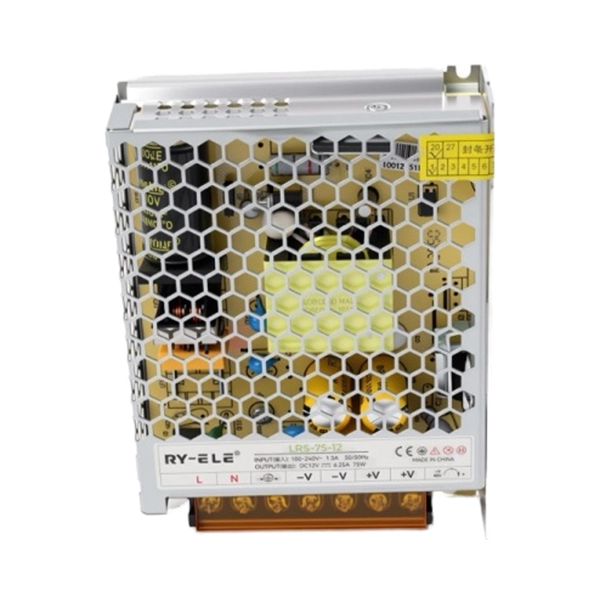
A power distribution unit (PDU) is a device fitted with multiple outputs designed to distribute electric power, especially to racks of computers and networking equipment located within a. Data centers face challenges in power protection and management solutions. This is why many data centers rely on PDU monitoring to improve efficiency, uptime, and growth. For data center applications, the power requi.
[PDF]
It consists of a lever or knob that can be turned to switch off the power supply to a particular circuit. It works by isolating a particular circuit from its power source, making it possible to work on the circuit without any risk of electrical shocks. Rotary. Our guide focuses on rotary switches, explaining their uses, how they work, and the different types available. What is a Rotary Switch? Rotary switches can be explained relatively easily. Many devices and circuits require switches with multiple available positions, to select different electrical. The rotary switch is a type of electrical switch and a primary electromechanical device that is utilised to regulate a number of circuits by rotating the switch's actuator only. A rotary switch may be more complex than a simple switch that is designed to have only two states – on and off. There are also two types of rotary switch structure, unipolar, single-position structure and multi-pole, multi-position structure. Single-pole, single-position rotary switches are often used.
[PDF]
The term 10G optical module generally refers to hot-pluggable transceivers in SFP+ form factor that support 10 Gigabit Ethernet (10GbE) transmission. A typical 10G SFP+ transceiver integrates a laser transmitter, a photodiode receiver, and a control IC within a compact housing. 10GBASE-LR is a 10-gigabit Ethernet optical standard that operates at 1310 nm over single-mode fiber (SMF), supporting link distances of up to 10 km. It is typically implemented using SFP+ transceivers and defined under IEEE 802. 10G-LR module has become one of the most widely. What is SFP? SFP refers to the small form pluggable factor. In actuality, it is a form of 10 Ethernet Transceiver that enables both: With these features, you can manage high data speed. The SFP works with small form factors (SFF) connectors that ensure high data speeds and physical compactness. So. As enterprises migrate to high-bandwidth environments, 10G optical modules remain one of the most widely adopted solutions for data centres, enterprise backbones, and metropolitan networks. However, facing the numerous models on the market, such as LRM, SR, LR, ER, ZR and other optical modules, how to choose the most suitable. High-speed data transmission in enterprise and data center networks is driven by 10G optical modules. Choosing the proper SFP+ module, whether it be SR, LR, or ER, can have significant impacts on performance, reliability, and costs.
[PDF]
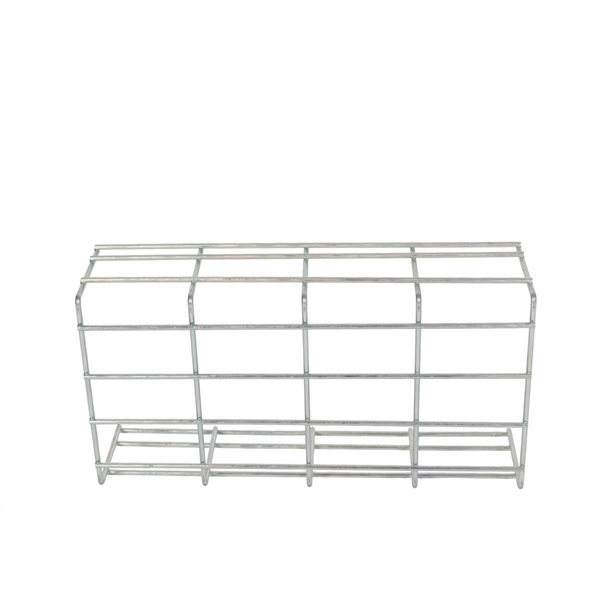
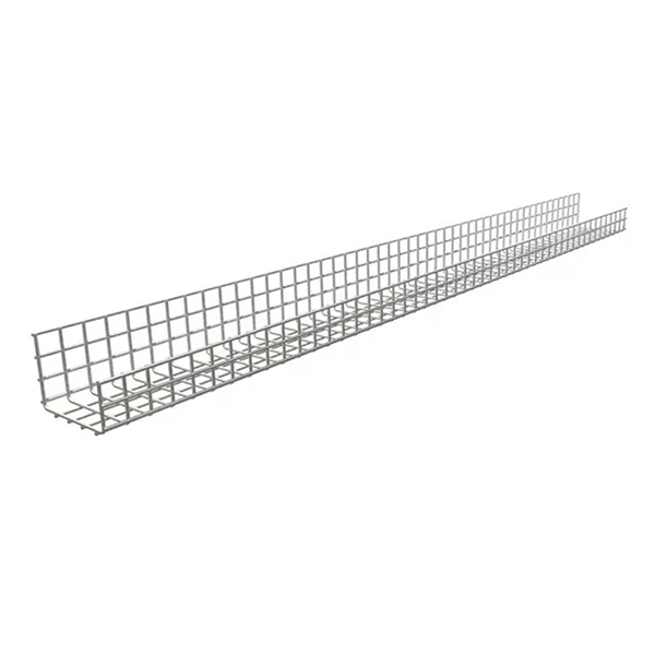
The formula to calculate the cable tray capacity is: [ CTC = text {floor}left (frac {W cdot H cdot FR} {CA}right) ] Where: ( CTC ) is the cable tray capacity (number of cables). ( W ) is the width of the cable tray (inches). ( H ) is the height of. This calculator determines the maximum number of cables that can be safely housed within a cable tray based on its dimensions and the cross-sectional area of the cables. Properly calculating cable tray capacity is crucial for ensuring efficient airflow, preventing overheating, and maintaining. Calculate the appropriate cable tray size based on your cables and fill requirements. This calculator determines if your tray meets industry standards (typically 30-50% fill for alternating single-layer or 40-50% for random arrangement). ( FR. The right cable tray sizing calculator helps engineers turn cable schedules into a verified tray width and fill check before material ordering and site installation. IEC 61537 covers cable tray and cable ladder systems for the support and accommodation of cables, while NEC Article 392 governs cable. In practice, cable tray dimensions are a system of interrelated measurements —width, depth, length, and material thickness—that directly affect cable fill compliance, heat dissipation, structural loading, and long-term expandability.
[PDF]

Generator protection relays are devices that detect abnormal operating conditions and isolate the generator from the system to prevent damage. These relays act as the first line of defense and are installed with strict adherence to IEC Standard for Protection Relays. Protecting generators from different electrical, mechanical, and thermal stresses is known as generator protection. To safeguard machines from overloads and unusual circumstances, preventive measures are required. Faults are inevitable even with effective design, construction, and operation. Below is an overview of the different types of relays used in generator systems, their functions, and their specific applications. Electromagnetic relays use. Generator Protections are broadly classified into three types: Class A, B and C. Class A covers all electrical protections for faults within the generating unit in which generator field breaker, generator breaker and turbine should be tripped. What Are Generator Protection Relays? Generator protection. There are various protection relays and those are used for protection against a wide variety of conditions. The fundamental principles that are covered in this course are equally applicable to. IEEE C37. 2 defines the IEEE “numerical” function designation for all protective relay functions. This presentation primarily uses the designations from the Beckwith M-3425A relay, which in most cases follows IEEE C37.
[PDF]
Fiber optic connectors in SFP modules are the physical interfaces that connect the transceiver to fiber patch cables, enabling optical signal transmission between network devices. Fiber optic connectors are silently the hero that make fiber networks to have secure, low loss, and easy maintaining connections. In their absence, it would be the only possible approach, splicing that is, which, indeed, is costly and time consuming besides irreversible. These connectors play a. A fiber optic connector is a mechanical device used to align and join optical fibers, enabling light to pass through with minimal loss. This allows for quickly connecting and disconnecting of fiber optic cables without splicing.
[PDF]
The AWGs are used to multiplex channels of several wavelengths onto a single optical fiber at the transmission end and are also used as demultiplexers to retrieve individual channels of different wavelengths at the receiving end of an optical communication network. Arrayed waveguide gratings (AWG) are commonly used as optical (de)multiplexers in wavelength division multiplexed (WDM) systems. These design of these devices are based on an. A 32-channel 50-GHz spaced arrayed-waveguide grating with our innovative configuration has been designed and fabricated. The performance of the device has been fully tested by using a tunable laser light source, optical power meter, and polarization controller. AWG has filtering characteristics and versatility, which can obtain a large number of wavelengths and channels, to realize the multiplexing and demultiplexing. The arrayed waveguide grating (AWG) is a planar versatile light-dispersion component with high accuracy, robustness, and design flexibility. It has become an attractive component not only for telecommunication (e., multiplexer or demulti-plexer)[2,3] but also for medical imaging,[4–6]. uide Grating Routers (WGRs). The acronym AWG, introduced by Takahashi , is the most frequently used name today and wi l also be used in this text. Together with Thin-Film Filters and Fibre Bragg Gratings, AWGs are the most important filter type applied in WDM networks, and with the advance of.
[PDF]
An optocoupler is a coupling device used to couple optical signals. It's primarily employed to combine and split signals in optical networks, and it's also referred to as a directional coupler. Image alt: Optocoupler-Optical coupler The figure above depicts a 2x2 coupler with two input ports and. It is widely used for coupling or splitting light waves through waveguides or fibers and can be availed in the form of either active or passive devices. The main difference between active and passive couplers is that the passive coupler redistributes the optical signal without converting optical. Optical couplers, essential components in the realm of fiber optics and telecommunications, stand at the forefront of enabling efficient, versatile, and reliable optical signal processing. In ophthalmic imaging; the coupler: A-Z > O > What Is an Optical Coupler? Share Provide a valuable. A coupler is an optical device that combines or splits optical signals. The basic principle of a coupler is to transfer optical power from one or more input ports to one or more output ports.
[PDF]
Fiber optic pressure sensors operate based on the principle of light modulation in optical fibers. When pressure is applied to the sensing element, it changes the properties of the fiber, such as the refractive index or the intensity of the light. These sensors are gaining popularity. Fiber-optic sensing (FOS) technology has emerged as a cutting-edge research focus in the sensor field due to its miniaturized structure, high sensitivity, and remarkable electromagnetic interference immunity. Compared with conventional sensing technologies, FOS demonstrates superior capabilities in. This article explains the structure, working principle, advantages, and disadvantages of Fiber Optic Pressure Sensors. Compared to traditional electronic pressure sensors, they offer advantages such as immunity to. Fiber optic pressure sensors are transforming how industries monitor and manage critical systems. Unlike traditional sensors, these devices use light to measure pressure changes, offering high accuracy, immunity to electromagnetic interference, and durability in harsh environments.
[PDF]
Fiber Bragg grating (FBG) sensors have emerged as advanced tools for monitoring a wide range of physical parameters in various fields, including structural health, aerospace, biochemical, and environmental applications. A fiber Bragg grating (FBG) is a type of distributed Bragg reflector constructed in a short segment of optical fiber that reflects particular wavelengths of light and transmits all others. This is achieved by creating a periodic variation in the refractive index of the fiber core, which generates a. A Fiber Bragg Grating (FBG) sensor is a specialized device that uses light within a glass fiber to detect environmental changes. This review provides a comprehensive overview of FBG sensor technology. Fiber Bragg grating (FBG) optical sensors have emerged as a leading technology for distributed strain and temperature measurement. Their unique attributes—compactness, immunity to electromagnetic interference, and multiplexing capabilities—make them a compelling choice for industries ranging from. Optical sensors based on Fiber Bragg Gratings (FBG) are becoming increasingly popular.
[PDF]

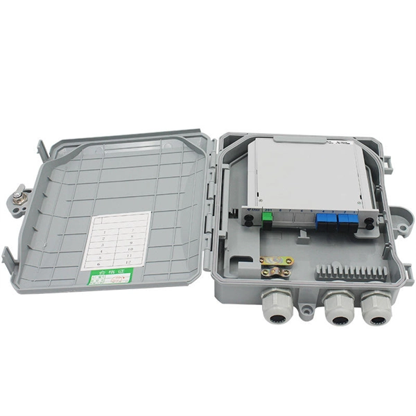
A FOSC is a protective enclosure designed to house, organize, and environmentally seal optical fiber splices, providing mechanical protection, water resistance, and easy re-entry for maintenance. At the core of this system's precision and reliability are Fiber Optic Splice Boxes—the unsung heroes that house and protect the delicate junctions where fiber cables are joined. The integrity of these enclosures is paramount to network performance. This guide optimizes the original text by delving. A splice box (also known as splice distributor) is a housing in which fiber optic cables begin or end. The main components of a splice box are the splice cassette that picks up the fibers and. Optical cable joint box The optical cable joint box permanently connects two optical cables together and has a joint part for protecting components. The optical cable connection part, that is, the optical cable joint, is the part that protects the connection between two or more optical cables by the optical cable. In the fast-evolving world of fiber optic networks, where FTTH connections surpass 2 billion globally and 5G/50G-PON deployments accelerate, one component quietly ensures long-term reliability: the Fiber Optic Splice Closure, commonly abbreviated as FOSC. Optical cable splice boxes protect the splicing parts of optical fibers from various hazards, such as water seepage due to adverse.
[PDF]