This guide explains how to make 90° bends, vertical bends, tees, and offsets in wire mesh cable trays safely and professionally. Horizontal 90° Bend (Flat Bend) 2. Tee (T-Junction) Bend 4. Since the jaws of the bolt cutter drags a layer of zinc across the cut end and forms a protective layer. When a wire cable tray is cut, the fact that a. Wire mesh cable trays are widely used because of their flexibility and easy on-site modification. Unlike perforated trays, bends can be created directly at site without expensive fittings. Great if you are new or just forgot how to do it, this easy to follow guide makes it so simple. more The Easy Guide to. This involves a few essential steps to ensure a successful bending process. The first step in preparing the. The method for producing bridge bend elbows is as follows: Take a 90-degree cable tray bend elbow as an example, and apply the same principles for 45-degree bends accordingly. The length of the bottom side (bottom diagonal) after bending the cable tray should be equal to the width of the cable. OTHER THAN 90 ̊ JUNCTIONS Use this guide to learn the most effective installation practices when installing Cablofil tray. Each example of bends and tee's clearly illustrate proper tray cutting combined with recommended usage of Cablofil accessories. Engineers and contractors in North America and.
[PDF]
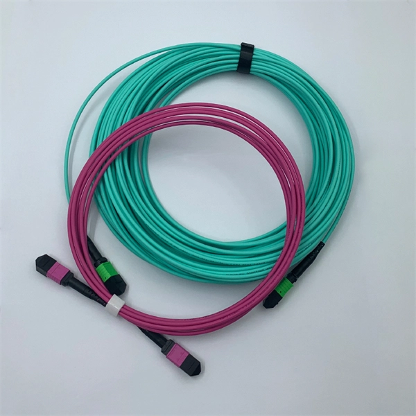
Power consumption of fiber optic cables can range from 0. 01-100 W/Gbps depending on the length of the cable (chart below). To ensure that fiber-optic connections have sufficient power for correct operation, calculate the link's power budget when planning fiber-optic cable layout and distances. The power budget is. Attenuation is the difference between the launch power of the signal from the transmitter and the power of the signal at the receiver. Each. The power consumption of coherent fiber-optical communication systems is beco-ming increasingly important, for both environmental and economical reasons. The data traffic on the Internet is increasing at a faster pace than that at which optical network equipment is becoming more energy efficient. With the growing global deployment of Fiber-to-the-Home (FTTH) networks driven by the demand for ensuring high-capacity broadband services, mobile network operators (MNOs) face challenges of excessive energy consumption (EC) of wired optical access networks (OANs). You use power budget calculations to verify whether an optical link—FTTH, ODN, backbone, or data center—can operate reliably under all. Reduced power consumption: 800G optical devices can achieve energy savings at the optical and system level, such as using more efficient modulation formats, optimizing circuit design, and reducing power density.
[PDF]
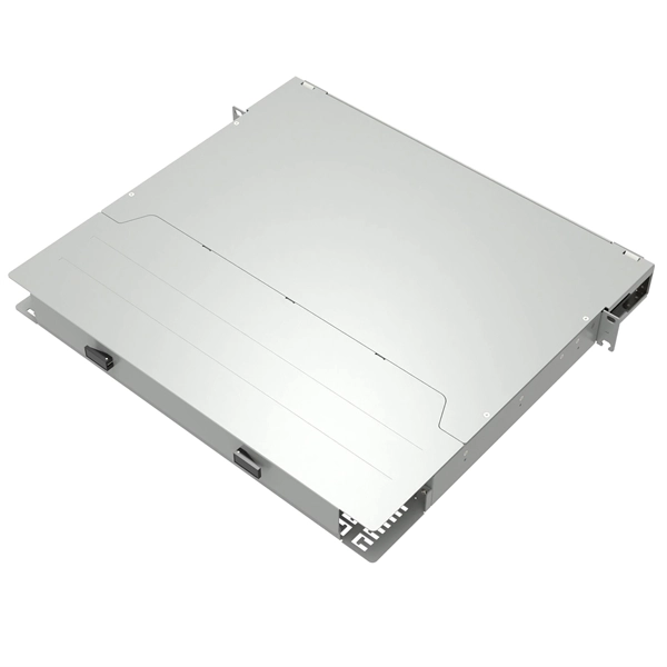
This guide provides instruction on how to install and configure your MS130R series switch. For more switch installation guides, refer to the switch installation guides section on. This guide provides step-by-step instructions for installing two common types of industrial switches: rack-mount, and DIN-rail switches. Choose the Installation Location: Select an appropriate spot on the DIN rail for mounting. This chapter describes how to start your switch and how to interpret the power-on self-test (POST) that ensures proper operation. No prior experience needed—just follow along and you'll have your switch installed and running in minutes. more In this video you'll see a complete, step-by-step guide to mounting. This typeface indicates command syntax, or represents information as it is displayed on the screen. When you see the word enter in this guide, you must type something, and then press the Return or Enter key. Do not press the Return or Enter key when an instruction simply says type. Here, we explore the four most common installation methods for industrial switches: Desktop installation is the most straightforward approach— placing the switch like a small box directly on a table, control panel surface, or equipment rack without extra fixtures. Simple setup: No tools required.
[PDF]
Housing Integrity: Cracked, melted, or physically broken outer casings. Electrical Failure: Severe internal burn marks or "fried" traces that prevent a safe rebuild. Completeness: Units that have been scavenged for internal parts or are missing proprietary hardware. This document describes how to identify, isolate, and troubleshoot symptoms of hardware failures on Catalyst 9600 Supervisors and Line Cards. There are no specific requirements for this document. The information in this. If the switch has rebooted unexpectedly, you can follow the steps to troubleshoot the hardware. If your core looks different. This topic covers the steps for troubleshooting bootup, crash, network, software, and audio issues related to the Q-SYS Core 110f processor and Cinema Core 110c processor. It details what information to collect post-event to help identify the root cause. Requirements and Components Used Requirements: None specific to hardware/software versions. Lab. Hardware faults on CE switches include power supply faults, fan faults, card power-on failures, unexpected card restarts, abnormal optical module status, and abnormal interface status. The following information helps you quickly locate hardware faults. Common Causes of Power Supply Faults Common.
[PDF]
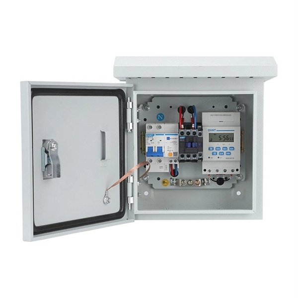
BSLI is an original equipment manufacturer (OEM) of custom electrical power distribution products. BSLI guarantees its customers fast, personalized service, quality components, and custom-designed equi.
[PDF]

This AutoCAD DWG file includes a complete Single Line Diagram (SLD) of a Distribution Board, showing circuit breakers, wiring connections, and load distribution for lighting, power, and mechanical systems. Knowledge of the basic electrical power distribution system and its components will help the operator understand the importance of electrical power distribution systems. Failure-free power e. Overlapping protective zones a. Protective relays A single, or one-line. A power distribution box (also called PDU or distro) directs electricity from a main source to multiple circuits. It acts like a hub or traffic controller, managing power flow to different areas or devices. Key components include circuit breakers, fuses, bus bars, and internal wiring for safety and. Check electrical parameters: First understand the basic electrical parameters of Distribution box so that you can have a general understanding of the capacity and performance of the distribution box. Analyze the incoming line part: Determine the incoming line source of the distribution box and. ndards and conformity assessment activities in the United States. ANSI facilitates and promotes voluntary consensus standar rty or economic loss due to fire, electrical and related hazards. Now, let's look at how consumers use electrical power. What is a Electrical Power Distribution System? 1. Power supply is received from LT panel and distributed to the outgoing feeders for utilization.
[PDF]
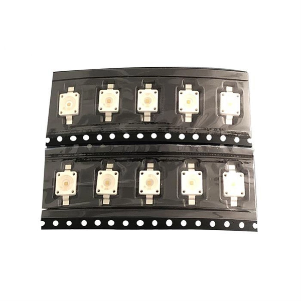
Silicon photonics is transforming AI computing by enabling energy-efficient, high-speed data transmission. Discover how optical interconnects present a possible solution to the data center energy crisis and drive sustainable innovation. Lam Research is setting the agenda for the wafer fabrication equipment industry's approach to a silicon photonics revolution, driving the breakthroughs in Specialty Technologies that will enable sustainable AI scaling through precision optical manufacturing. The artificial intelligence boom has. y with vastly reduced energy con-sumption by integrating optics deeply within computing sockets. We present the design and characterization of a dense wavelength-division multiplexing (DWDM) SiPh transceiver chip, featuring a unique architecture in the multi-FSR regime and targeting a shoreline. Silicon photonics is becoming a critical enabler of AI and HPC, breaking the limits of electrical interconnects in bandwidth, distance and power efficiency. Co-packaged optics (CPO) builds on silicon photonics, with SiPh transceivers as the integration platform and CPO as the packaging architecture. Silicon Photonics emerges as the solution to this predicament, replacing electrons with photons—the fundamental particles of light—to race across familiar silicon-based chips, promising a revolution in computing and communication. This isn't just about increased speed; it's about a profound impact.
[PDF]

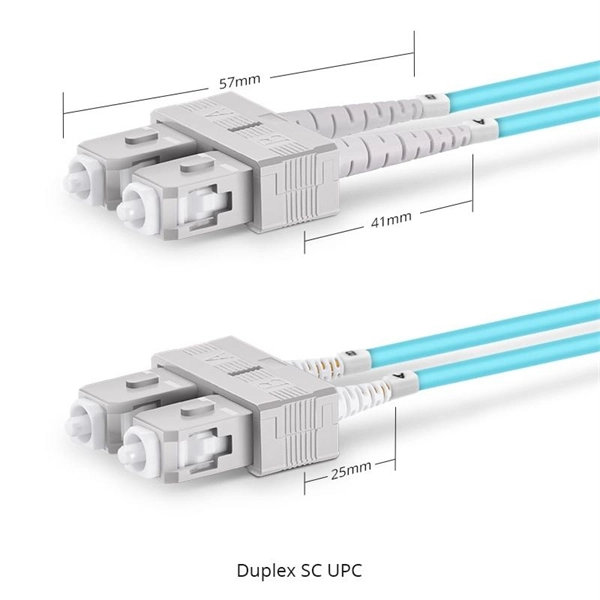
To use a power meter for fiber optic testing, always clean connectors first with lint-free wipes or click-to-clean tools. Select the correct wavelength and set your reference. You measure optical power in dBm or insertion loss in dB. Consistent procedures ensure accuracy. Verify light travels from. The most basic fiber optic measurement is optical power from the end of a fiber. This measurement is the basis for loss measurements as well as the power from a source or presented at a receiver. Typically both transmitters and receivers have receptacles for fiber optic connectors, so measuring the. An optical power meter measures the strength of light traveling through a fiber optic cable, giving you a reading in dBm (decibels relative to one milliwatt). This article will guide you through the methods, instruments, and key considerations for measuring fiber. Fiber optic cabling is the high-performance core of today's datacom networks. As network speeds and bandwidth demands increase, fiber performance requirements have become more stringent. Fiber testing is more important than ever. An OPM uses a photodiode to generate an electrical current proportional to optical power.
[PDF]
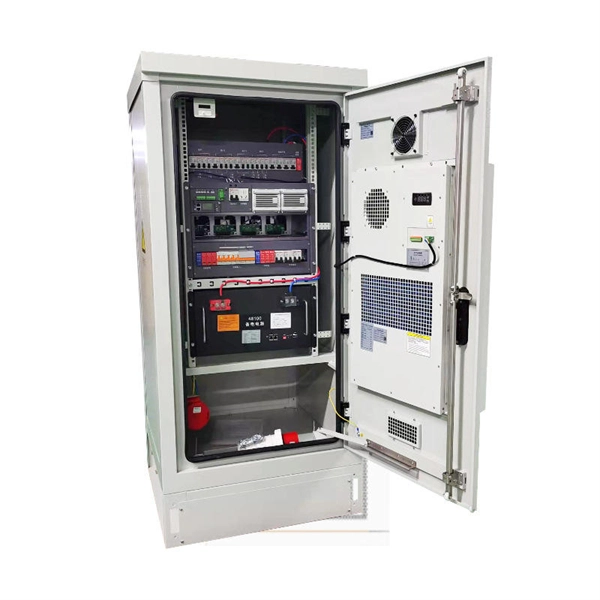
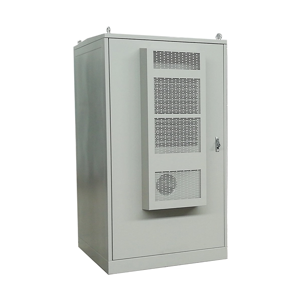
Source over 3551 outdoor power supplies for sale from manufacturers with factory direct prices, high quality & fast shipping. An outdoor power supply cabinet is a protective enclosure designed to house and safeguard electrical components in external. On plans, consult us to know our prices and compare them. MECHANICAL FABRICATION: - All types of materials: Steel, Stainless Steel. CRP Transmission: Your Expert in Custom Electric Cylinders Founded in 1989 by Hubert Kufel, CRP Transmission specializes in the custom manufacturing of electric. There are 11 products. Labérine distribution cabinets guarantee protection against the risks of electrocution and short-circuits, eliminating the potential hazards associated with inferior models. These cabinets are engineered to. They exclude delivery charges and customs duties and do not include additional charges for installation or activation options. Prices are indicative only and may vary by country, with changes to the cost of raw materials and exchange rates. Designed, tested and compliant with the highest industry operating standards, Alpha outdoor enclosures are equipped with control systems that maintain.
[PDF]

In this video, we'll show you how to connect an energy meter to a distribution board (DB) safely and efficiently. energy meter connection with distribution box How to Connect an Energy Meter to Your Distribution Box Easily Steps to Properly Connect Your Energy Meter to a Distribution Box. It plays a vital role in ensuring the safe and efficient distribution of electricity throughout the premises. What is the wire from the meter to the breaker box? Also. Always begin with disconnecting the main supply before accessing any enclosure containing distribution components. This prevents arc faults and ensures safety when modifying or inspecting current paths. This “meter to panel” wiring establishes the pathway for all incoming electrical power from the grid to the home. Its primary function is to safely and reliably. Distribution Board aslo know as “Panel Board”, “Switch & Fuse Board” or “Consumer Unit” is a box installed in the building containing on protective devices, such as circuit breaker, fuses, isolator, switches, RCDs and MCBs etc. The electric main supply (230V AC & 120V AC in US) is connected through. Changed Texas's reference diagram for the 3 wire network 120/208 Volt single phase self-contained Revised Figures 13, 14, 14b. Limited the meter location from pad mount transformer for PSO. Removed unistrut being listed as an alternative means for mounting the meter box. APCo and TX do not allow.
[PDF]
Incoming power wires must use conduit connections on the bottom plate of the MCC structure to enter the ArcBlok-equipped main circuit breaker unit. A distribution box is the heart of any electrical system. Whether in a home or an industrial facility, this box keeps your electrical setup organized, functional, and efficient. However, the key to. Start by shutting off power at the main disconnect to prevent shock hazards. Remove the panel cover to access internal conductors. Line terminals, typically located at the top of the enclosure, receive incoming service from the utility. These are usually connected to thick black or red wires, each. These boxes full of circuit breakers or fuses distribute incoming power to wiring circuits throughout the house. Top-feed MCC main circuit breaker units with ArcBlok 1200 include a required, 18 in. Commercial line box: Designed for commercial facilities such as office buildings and shopping malls, it has a larger carrying capacity and.
[PDF]
This video shows real on-site footage of electrical installation, demonstrating safe and standardized wiring methods used by professionals. An electrical distribution box, also known as a power distribution box, panelboard, or consumer unit, is the core of an electrical system. It has three categories: residential, commercial and industrial electrical distribution boxes, all of which play important roles in their respective electrical. Learn how to install a distribution box safely and correctly. Covers wiring, placement, standards, and expert tips for a compliant setup. It takes the incoming power and safely distributes it to different circuits throughout your building. more Learn how to wire a distribution box step by step! This video shows real on-site footage of. A distribution board or distribution box is where the main power supply is distributed to multiple loads. And all the switching and protective devices are installed in the distribution box. Single Phase Distribution Box generally consists of Double Pole MCBs, Single Pole MCBs, and RCCBs. Unlike single-phase systems, where power is distributed using. Phase 3's Powersafe Sequential Mating Box controls the connection sequence of incoming / outgoing high current cable connections. The sequence ensures that the Earth connection is made first and disconnected last. (FMLB- First Mate Last Break). With key (included) turn the Earth lock clockwise (Fig.
[PDF]

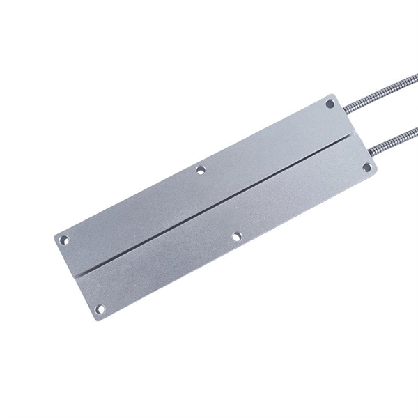
In this complete wiring diagram guide, we will walk you through the step-by-step process of wiring a mag starter. We will explain the purpose and function of each component, provide clear diagrams, and offer expert tips to ensure a successful installation. Whether you're a beginner or an. For proper integration of an electromagnetic securing device, ensure the power supply matches the specified voltage–typically 12V or 24V DC. Incorrect voltage can cause malfunction or reduced holding force. Use a regulated power source to prevent current fluctuations that might trigger false alarms. Understanding the wiring diagram of a magnetic starter is essential for technicians and electricians who work with electric motors. This diagram provides a visual representation of the components and connections involved in the operation of the starter. Once you have everything ready, you can proceed with the installation process. Begin by determining the appropriate position for the magnetic lock on the door. Quick guide on how to wire an access control system with power supply, lock, and exit button. more Quick guide on how to wire an access control. Installing a magnetic door lock can be a cost-effective and reliable way to secure your doors. These locks use an electromagnetic current to keep the door securely closed, and they are commonly used in commercial and residential buildings.
[PDF]
CIF Incoterms is one of the most commonly used terms in international trade transport. Having a deep understanding of its meaning, usage scenarios, price calculations, and other aspects can be extremely helpful for practical trade. Below is a detailed introduction to CIF. Search from Thousands of Senegal Tenders, Bids, EOIs and RFPs. You are Successfully Registered to SenegalTenders!! Recruitment of a service provider for the organization of a holiday camp for the benefit of the children of personnel of the Société Africaine de Raffinage (SAR). The service provider. Cost, Insurance and Freight (CIF) is an Incoterm rule that is identical to the CFR Incoterm rule except in one aspect: insurance. Even though the risk transfers to the seller upon loading the goods on board the vessel, in CIF, the seller is obliged to take out insurance cover for the buyer's risk. This term not only determines the total cost of goods but also impacts decisions related to logistics, pricing, and risk management. In this guide, we'll break down what CIF means, how it's calculated, and. Subscribe to get Senegal government tenders, Bids, RFPs and eProcurement notices from the biggest online database of Senegal. We suggest you read it.
[PDF]
Through a real deployment case using E-abel server cabinets, we illustrate how cabinet design and connector architecture improve power reliability, reduce maintenance complexity, and support the increasing power density of modern data centers. Managing and installing a rack power distribution unit (PDU) has never been easier than with the EL2P PDU. Designed to simplify deployment and take stress out of power distribution, this intelligent PDU helps reclaim valuable hours. Whether that means speeding up Saturday installs or focusing on. An Intelligent Power Distribution Unit (iPDU), also known as a Smart PDU or Intelligent PDU, is a critical component in modern data center infrastructure. The units are available in horizontal 19-in. rack or vertical mounting capabilities. Why Has the Selection of Rack PDUs Become So Important?. For power distribution requirements of medium to large data centers, Delta's Power Distribution Unit (PDU) is an optimal solution. The space-saving PDU is easy to move and adapt to the future demands of the data center. The PDU offers superior power protection and monitoring, and the flexibility. Modern infrastructures typically rely on rack-level Power Distribution Units (PDUs), industrial CEE connectors, and structured cabinet designs to manage power connections efficiently. This article explores how power is connected inside modern data center racks, examining the flow of electricity.
[PDF]