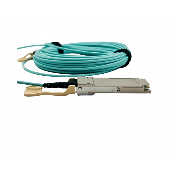
A fiber-optic switch allows you to connect two or more fiber-optic cables to form a network. These can behave like a typical Ethernet switch. With a fiber switch combined with a fiber network adapter, you could connect fiber directly to your desktop computer or. Multimode fiber (MMF) is an optical fiber designed to carry multiple light propagation paths—or modes—simultaneously. This is made possible by its relatively large core diameter, typically 50 or 62. 5 microns, compared to the ~9-micron core in single-mode fiber. The wider core accepts light from. Multi-mode optical fiber is a type of optical fiber mostly used for communication over short distances, such as within a building or on a campus. Multi-mode links can be used for data rates up to 800 Gbit/s. Assuming Auto-MDIX is not enabled on these devices, drag the appropriate type of cabling on the left to each connection type on the right. In this blog post, we will discuss the key features and. This article describes the common types of fiber optic cable used for data transmission. Ubiquiti also provides branded optic SFP/SFP+ modules (tranceivers) that are fully compatible with all of our devices. See the page for more information. Back to Top Fiber optic cabling is an alternative to.
[PDF]

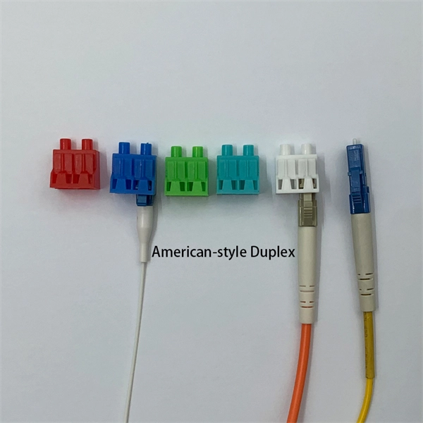
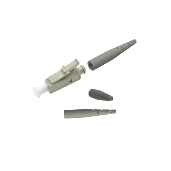
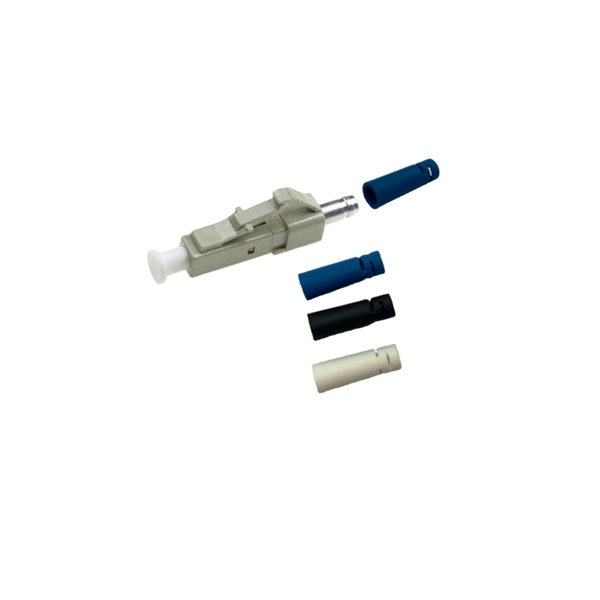
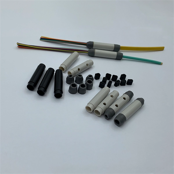
Fiber optic pigtails are short, single, or multi-strand pieces of optical fiber cables with a connector on one end and exposed fiber on the other end. They are typically used to terminate fiber optic cables and connect them to patch panels, equipment, or other termination points. Fiber pigtails are simple in appearance, yet essential in function. Despite this ubiquity, they remain a source of confusion for procurement teams and junior installers alike—especially when it comes to connector type selection, polish type, and the tradeoffs between mechanical. Fiber Optic Pigtails, also known as pigtailed fibers, consist of an optical fiber connector and a section of optical cable. Characterized by having an optical fiber connector on one end and a bare fiber end on the other, they are primarily used to connect optical transceivers or other optical. A Fiber Optic Pigtail Complete Guide: As per types, connectors, and applications. In such contemporary fiber optic communication systems, low-loss, and connectivities, which have reliability, are crucial for not only maintaining high-speed but also high-quality data transmission. It is usually suitable for field termination using a mechanical or fusion splicer. Compared with quick termination or epoxy and polish connections placed on the field.
[PDF]

Some of the most common optical passive components include optical couplers, optical splitters, optical filters, optical connectors, optical attenuators, optical circulators, optical isolators, optical switches, and optical add/drop multiplexers. Optics engineering focuses on transmitting data using light, a method providing the high speeds and vast bandwidth necessary for modern digital life. Passive optical components play a fundamental role within this infrastructure. These engineered devices manage and direct light signals through a. A passive optical network is a point-to-multipoint network architecture to serve multiple premises. It allows communication service providers to serve several customers using a single connection. There is no need for any active components for electrical-to-optical or optical-to-electrical. Passive optical components play a pivotal role in high-speed, long-distance communication networks, such as fiber optic networks, to ensure efficient and secure data transmission over vast distances without the need for external power supplies.
[PDF]
Key techniques include using bonding agents, saw-cutting, re-pouring concrete, mechanical connectors, and epoxy injection. Conventional methods like epoxy grout injection can address cracks effectively. Learn how to prep and bond a next-day concrete pour to repair a cold joint. This guide walks through practical surface prep, bonding methods, and timing so you can create a strong, durable joint. You'll gain actionable, plain-language steps and tips you can apply on real job sites. Identify cold. A cold joint is a common imperfection in concrete construction, occurring when fresh concrete is poured next to a section that has already begun the setting process. This discontinuity prevents the two pours from chemically integrating into a single monolithic unit, creating a weak plane within the. A cold joint in concrete is an area or surface with a structural discontinuity caused by the delayed concrete pouring between two layers of concrete. This issue compromises the structural integrity and durability of the concrete. This transition from a plastic or fluid state to a semi-solid state creates a discontinuity.
[PDF]
Lumentum manufactures indium phosphide (InP) directly-modulated lasers (DMLs) in our internal wafer foundry. These DMLs are based on the distributed feedback (DFB) diode lasers. With a DFB, a distributed Bragg reflector is used to accurately lock to the desired wavelength. BAHAMAS DAY SPA, INC. BAHAMAS ELITE. Thorlabs' collection of components and systems below are designed to actively manipulate the properties of input light. This Notice provides information on the approval standards for individual items of marine equipment provided on board Bahamian ships to meet the requirements of International Conventions and which are required to be “approved by the Administration”. With the DML, the laser. Diagnostic instruments, reagents, and medical equipment from 57 + manufacturers — delivered, installed, and serviced across 33 Caribbean territories. Latest-generation dedicated HbA1c HPLC analyzer. The ARGOS® Biometer with Image Guidance by Alcon is the smarter planning solution that keeps efficiency and accuracy flowing through your clinic. * Compared to VERION® Reference Unit. * Trademarks are the property of their respective owners. ‡ With capture times as low as 0.
[PDF]
In, a protective relay is a device designed to trip a when a is detected. The first protective relays were electromagnetic devices, relying on coils operating on moving parts to provide detection of abnormal operating conditions such as over-current,, reverse flow, over-frequency, and under-frequency.
[PDF]

This handbook covers the code of practice in protection circuitry including standard lead and device numbers, mode of connections at terminal strips, colour codes in multicore cables, dos and donts in execution. Also principles of various protective relays and schemes including special protection. Read this document and the documents listed in the additional resources section about installation, configuration, and operation of this equipment before you install, configure, operate, or maintain this product. Users are required to familiarize themselves with installation and wiring instructions. presentation of protection and control relaying. The report will identify methodology behind these practices, present issues raised by the integration of microprocessor relays and the internal logic and external communication configurations, ying. The objective of this presentation is to convey a basic understanding of protective relays to an audience of engineers already familiar with low voltage protective device coordination. HT panel protection relay. The HT power supply is received from GO switch and distributed to the. The handbook for protection engineers includes guidelines on protective circuitry, protective relay principles, and testing procedures for switchgear and relays. It covers standard codes, wiring practices, and norms for protecting generators, transformers, and lines, and provides detailed.
[PDF]

Unlike traditional point-to-point fiber connections, PON systems distribute optical signals from an optical line terminal (OLT) to many optical network units (ONUs) or optical network terminals (ONTs) without requiring active electronic equipment in the distribution network.StatusIn forceYear started2003Latest version(07/10) · July 2010OrganizationOverview G.984 is the series of standards that define the architecture and operation of -per-second–capable (GPON). It is commonly used to implement the link to the customer (the. GPON uses passive optical network (PON) is a access in which a single optical fiber from a central location is shared by multiple end users through one or more in series (cascaded). The standard specifies transmission convergence layer, physical layer requirements, management protocols, and service encapsulation for high-speed fiber access networks. GPON put. In contrast to technology, which deteriorates as the distance between the central office and the household rises, with severe signal loss beyond 3km, all customers may enjoy high-speed network access with.
[PDF]
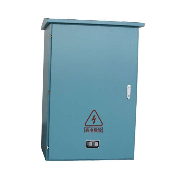
Fiber networks have become the cornerstone of modern broadband, delivering high-speed, reliable connectivity to homes, offices, and enterprises. In a Fiber-to-the-Home (FTTH) or FTTx network, devices like the Optical Line Terminal (OLT) and Optical Network Unit (ONU/ONT) often. ODN, or Optical Distribution Network, is an FTTH network based on PON equipment that provides an optical transmission channel between the OLT and the ONU. It is an integral part of the passive optical network (PON) system to facilitate the two-way transmission of optical signals. It directly. An Optical Distribution Network (ODN) is a component of modern optical fiber communication systems, serving as the intermediate layer between the central office or data center and the end-user premises. It links your service provider to your house with fiber cables. These cables carry light signals to send data. ODN is a passive network. This means it does not need power along the way. Over the past decade, and often out of the spotlight, ODNs have played a critical role in the widespread adoption and deployment of. Explore ODN and Quick ODN Architectures, Including Fiber Optic Cable, PLC Splitters, and Fiber Distribution Boxes for Efficient FTTH Network Deployment 1.
[PDF]
Finally, use the following formula to determine the busbar current. Calculate the current carrying capability of a 150 (width) x 25 (thickness) (in mm) busbar in the copper material. 2 Ibb = 4500A Click here for more Electrical Calculators IEC 60865-1:. Copper busbar current carrying capacity (ampacity) is the maximum electrical current a copper busbar can safely conduct without overheating or failure, a critical parameter for electrical panel and power distribution design. 2 and IEC 60364 standards ensures copper busbar. To calculate Busbar Current, enter the width (mm), thickness (mm), and material carry capacity factor (amps/mm^2). The electrical power system consists of many incoming & outgoing feeder connections, for which busbars are necessary. A busbar is just a node (conductor or collection of conductors). Even though a busbar looks like just a flat copper or aluminum strip, its size determines how much electrical load it can handle. If the size is too small, it can overheat, cause voltage drop, or even become a fire hazard. If it is oversized, it increases cost and space requirements unnecessarily. Busbars are critical components in electrical distribution networks, typically used to distribute high current among various circuits. 2 A/mm² for copper busbars in enclosed panels and up to 2. 2 Copper busbars have approximately 60% higher current carrying capacity than.
[PDF]
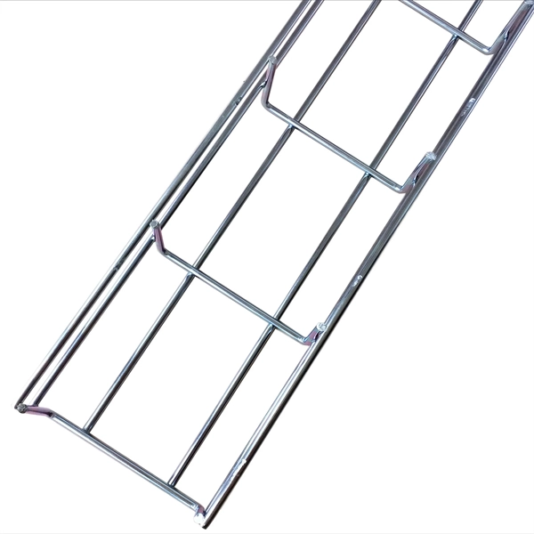
Cable tray pricing depends on materials, coatings, size, supplier margins, and order quantity —plus hidden costs like shipping and installation. This guide breaks down everything buyers need to know, from price trends to cost-saving tips. The cable ladder is named because its structure resembles a ladder, with a crossbar welded in the middle to reinforce the support. It is a bracket for supporting and placing cables, with the advantages of light weight, low cost, unique shape, easy installation, good heat dissipation and air. Trapezoidal cable trays are generally made of metal or aluminum, have excessive energy and corrosion resistance, and they can be custom-made as wished to meet exclusive cable routing needs. Trapezoidal cable bridge is a sort of cable bridge which is related by way of two longitudinal channels and. From design to sourcing, let Accio Work handle the heavy lifting. Boost your ROl today! Find products, communicate with suppliers, and manage and pay for your orders with the Alibaba. com app anytime, anywhere. Use this image search extension to find and compare similar products with wholesale. Find here Galvanized Cable Trays, GI Cable Tray manufacturers, suppliers & exporters in India. The average cable tray price per meter ranges from $2 to. How can we improve? Choose from our selection of cable trays, including over 850 products in a wide range of styles and sizes. Same and Next Day Delivery.
[PDF]
Answer: The current transfer ratio (CTR) is an important parameter in optocoupler selection. The gain of an optocoupler is expressed as the Current Transfer Ratio (CTR). It is defined as the ratio of the phototransistor output current (Ic) to the LED input current (If), expressed as. The current transfer ratio is a parameter similar to the DC current amplification ratio of a transistor (h FE) and is expressed as a percentage indicating the ratio of the output current (I C) to the input current (I F). The CTR has the following characteristics and is therefore as important as the. An optocoupler, also known as photocoupler or opto-isolator, is a device which can transfer an electrical signal across two galvanically-isolated circuits by way of optical coupling. Transferring signals over a light. As I understand the optocoupler current transfer ratio, CTR is like the hfe of a transistor. I can't understand if the CTR is or isn't a critical value and for what applications is it used in. Optocouplers contain both a light-emitting diode (LED) and a photo detector. The current transfer ratio. The current transfer ratio (CTR) refers to the ratio of the collector current at the output side I c to the input current passed to the LED at the input side I F expressed as a percentage. It is defined by the following formula.
[PDF]
Glass fiber and plastic fiber is fragile. When individual fibers break, light transmission and uniformity are reduced. After the first few fibers break at a stress point, a chain reaction occurs, hastening t.
[PDF]
A spot network typically comprises a secondary network that serves a singular, concentrated load, such as a high-rise building or shopping mall, necessitating a high level of reliability. The secondary spot netw.
[PDF]
Important transmission lines and generators have cubicles dedicated to protection, with many individual electromechanical devices, or one or two microprocessor relays.OverviewIn, a protective relay is a device designed to trip a when a is detected. The first protective relays were electromagnetic devices, relying on coils operating on moving par. Electromechanical protective relays operate by either, or. Unlike switching type electromechanical with fixed and usually ill-defined operating voltage thresholds.
[PDF]