The goal is to fuse the two fibers together in such a way that light passing through the fibers is not scattered or reflected back by the splice, and so that the splice and the region surrounding it are almost as strong as the intact fiber. Fusion splicing is the process of fusing or welding two fibers together usually by an electric arc. Fusion splicing is the most widely used method of splicing as it provides for the lowest loss and least reflectance, as well as providing the strongest and most reliable joint between two fibers. Fiber Stripping: Selecting Precise Tools and Techniques Selecting the appropriate stripper will depend on the fiber coating diameter. This will typically be 250µm for bare fibers and 900µm for coated fibers. Reputable companies like Jonard, Fujikura, and INNO provide multi-hole strippers calibrated. Fiber misalignment and fiber geometry mismatch (e., core size, core-to-clad concentricity, core and cladding non-circularity, numerical aperture, etc. ) can result in real power loss across a splice joint. However, differences in the backscattering coefficients between two fibers can also show up. Fiber splicing means joining two optical fibers (permanently or temporarily) such that light guided in one fiber and reaching the joint (splice) can be transferred into the second fiber with low insertion loss.
[PDF]

The formula for calculating electrical box size is: . The formula for calculating electrical box size is: . Free electrical load calculation tool for residential and commercial buildings. Calculate service entrance sizing, panel loads, demand factors, and ensure NEC Article 220 compliance. Important: Load calculations must comply with NEC Article 220 and local codes. Always verify calculations with a. How to choose a distribution box of the right size for a project based on load current? If you're like most electrical professionals, picking the right distribution box for your project can feel like navigating a maze. I've been in those shoes - staring at spec sheets, worrying about. The National Electrical Code (NEC) specifies minimum box sizes based on wire gauge and quantity. Proper sizing ensures safety, ease of maintenance, and compliance with regulations. This calculator helps you determine the minimum required box volume based on the number of wires, devices, ground wires, and clamps involved. This ensures compliance with electrical codes and prevents overcrowding. Choose a standard or custom box volume watch capacity update with clear pass or fail status plus tips examples CSV and PDF export for documentation Works for common sizes supports.
[PDF]
A transimpedance amplifier (TIA) converts an input current into a proportional voltage, typically using an inverting op-amp with a feedback resistor (Rf). TIAs present a low-impedance input for current-output sensors such as photodiodes, preserving linear conversion and bandwidth. TIAs are conceptually simple: a feedback resistor (RF) across an operational amplifier (op amp) converts the current (I) to a voltage (VOUT). A transimpedance amplifier (TIA) converts a current to a voltage and is often used with current-based sensors like photodiodes. It's also a common building block that helps explain the performance and stability limits of many other op-amp circuits. Despite or because of their simple topologies, TIAs pose rigid tradeoffs among their gain, noise, and bandwidth (BW). The fundamental operation relies on an operational.
[PDF]
This video shows real on-site footage of electrical installation, demonstrating safe and standardized wiring methods used by professionals. more Learn how to wire a distribution box step by step!. Explosion-proof distribution boxes, vital terminal distribution equipment in power systems, play a crucial role in controlling and protecting industrial electricity in hazardous environments. Given their ubiquity, let's delve into the installation and wiring of indoor distribution boxes today. Choose the right box based on environment (indoor/outdoor), load capacity, and durability. Check for proper IP/NEMA ratings and material quality. These panels are commonly installed in areas like detached garages, workshops, basements, or home additions to manage localized electrical loads. Whether you're an electrician or a DIY enthusiast, this guide will help you understand the basics of home electrical distribution. What is Distribution Board? Distribution board. Common NEMA ratings include NEMA 1 (for basic indoor protection) and NEMA 4 (for corrosion resistance). If your distribution box is installed outdoors and exposed to rain and sunlight, you need to select an electrical enclosure with a higher protection level, such as models with IP66 or NEMA 4.
[PDF]
Check for proper IP/NEMA ratings and material quality. Ensure safe placement: install in dry, accessible areas with good ventilation and at appropriate height (typically ~1. Practice good wiring: secure grounding, neat cable management, proper insulation, and correct wire gauge. In this video, we'll walk you through the process of wiring a home distribution box with a detailed connection diagram. Whether you're an electrician or a DIY enthusiast, this guide will help you understand the basics of home electrical distribution. more Welcome to our channel! In this video. However, the key to a safe and reliable system lies in proper installation. If it's done poorly, you risk short circuits, fire hazards, or system failure. Done right, it ensures safety, compliance, and long-lasting performance. In this guide, we'll break down everything you need to know to install. Distribution board is a safe system designed for house or building that included protective devices, isolator switches, circuit breaker and fuses to safely connect the cables and wires to the sub circuits and final sub circuits including their associated Live (Phase) Neutral and Earth conductors. Learn how to wire a single-phase household distribution box in just 60 seconds! In this quick tutorial, we'll cover the essential components and wiring steps for a safe and efficient distribution setup in residential areas.
[PDF]

This publication shows how to wire and install the 4010-9825 24V Distribution Block into a 4010 Fire Alarm Control Panel (FACP). Refer to the 842-058 Field Wiring Diagram for additional wiring information. 1 Transformer connection: Two red wires connect to AC 220V input port, while two yellow wires connect to AC input port of main board (had connected by the factory. 2 DC12V battery connection: Red wire on the circuit main board connects to the positive pole of acid-lead battery while black. Notify the carrier and call Telect's Customer Service Department at 1-800-551-4567. Keep the container until you have checked equipment operation. Use the original, undamaged container if you are instructed to return. Learn how to wire a distribution box step by step! This video shows real on-site footage of electrical installation, demonstrating safe and standardized wiring methods used by professionals. Such a system, however, does not assure. Material preparation: Prepare the required circuit breakers, wires, wiring ties and other materials, and ensure that they meet the design drawings and installation requirements. Location determination: Determine the installation position of the circuit breaker according to the position of the.
[PDF]

In the following tutorial, we will show how to wire 120V single-phase and 240V split-phase circuit breakers and loads inside a residential main panel. The figure below shows a typical breaker panel used for 120V and 240V circuits. Messy distribution boxes are dangerous and very hard to fix. You will learn to build a safe, efficient, and professional electrical system today. Circuit breaker wiring configurations involve organizing main switches, busbars. A breaker box, also known as a circuit breaker panel, is an essential component of any electrical system. It is responsible for distributing electricity throughout a building, ensuring that each circuit receives the proper amount of power. To understand how a breaker box works, it is helpful to. Each circuit is protected by a circuit breaker, a safety device that automatically shuts off power if it detects an overload or a fault. If you're looking to replace an old fuse box replacement or upgrade your home's power capacity, you'll be dealing with the load center or service panel. The distinction between 1P and 2P circuit breakers plays a pivotal role in determining the appropriate protection level for various circuits. When installing or troubleshooting a power distribution system, understanding how to correctly connect the main electrical supply to the control panel is crucial.
[PDF]
Connecting fiber optic cable directly to a standard Ethernet port is not possible. Ethernet ports are designed for copper cables (like Cat5e or Cat6), which transmit data using electrical signals. The process to connect fiber optic cable to router requires careful attention to detail, but I'll walk you through every critical step with the precision and clarity you deserve. This comprehensive guide combines industry standards with field-tested practices to ensure you achieve a rock-solid. In this guide, we'll walk you through how to connect a fiber optic cable to a router safely and efficiently. Why Use Fiber Optic Internet? Before diving into the setup, let's quickly recap why fiber optics are worth the effort: Lightning-fast speeds (up to 1 Gbps or higher). Here's a step-by-step guide to help you through it. Check compatibility: Before you begin, make sure your router supports fiber optic connection. Not all routers can connect directly to a fiber cable, so it is important to verify this information before continuing. Gather. Unlike regular electrical wires, these glass fibers can snap or bend too far. Proper connectors, clean ends, and a good splice keep everything sharp and stable. When you connect the fiber optic cable correctly, you keep your fiber internet, ONT (optical network terminal), and router running at peak. Connecting a fiber optic cable to a router involves a few key steps and specialized equipment.
[PDF]
A grid networks consist of an interconnected grid of circuits, energized from several primary feeders through distribution transformers at multiple locations. Grid networks are typically featured in.
[PDF]

This guide will walk you through the process of checking photo sensors using a multimeter, covering various types of photo sensors, the necessary tools and safety precautions, and the specific measurement techniques involved. Knowing how to effectively use a multimeter to test photo sensors can save you time, money, and frustration when dealing with malfunctioning devices. more What is a Voltage Divider? | What is a Voltage. Before replacing the sensor or fixture, it's efficient testing it first, With a few tools and a step-by-step process you can find whether your outdoor lighting control system is working as intended or if the problem lies elsewhere. In this complete guide from Lead-Top, a global leader in photocell. In this blog post, we explain step-by-step how to troubleshoot a sensor with a digital multimeter (DMM). Here are the steps: Troubleshooting a sensor measurement failure requires mechanical tools to uncover the protective shields or components so you can reach the sensor in question. Always follow the manufacturer's instructions for the sensor and multimeter. Ensure the sensor is properly connected to the multimeter and. A multimeter is an indispensable diagnostic tool for anyone working with electronics, electrical systems, or indeed, sensors. It's a versatile device capable of measuring voltage, current, and resistance, providing crucial insights into the health and functionality of electrical circuits and.
[PDF]

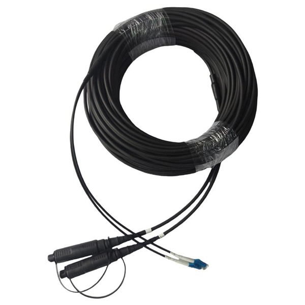
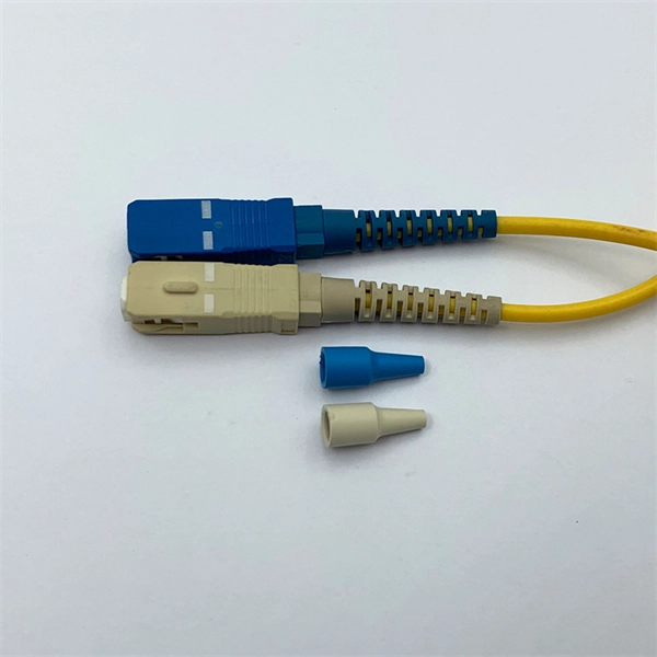
They are the bridge between fiber optic cables in the field and the equipment or patch panels that manage them. By combining factory-installed connectors with spliced bare fiber, pigtails ensure that network installers can create fast, reliable, and cost-effective terminations. Pigtail connections are most frequently used to ground a switch or electrical outlet and for electrical devices that need to connect to multiple circuit wires. A pigtail is composed of three strands of wire. We'll guide you through the fundamentals of creating secure links between multiple conductors and terminals. Pigtails act as bridges, allowing you to connect several wires to a single point without overloading connections. Professionals often prefer this method because it isolates issues. Fiber pigtails are simple in appearance, yet essential in function. It ensures a secure connection by combining wires with a wire connector, like a twist-on connector or a wire nut, and then linking them to the intended terminal or fixture. Pigtails serve. A pigtail wire is a short cable used to lengthen short wires. This pigtail technique is applicable in several home and automotive wiring projects, especially for circuit grounding wires. The National Electrical.
[PDF]

Optical modules convert electrical signals into light to move data quickly and reliably in AI systems, enabling fast and smooth data processing. Using advanced optical modules boosts AI system speed and bandwidth, helping handle large data loads with low delay and high efficiency. Optical modules. Laboratory utilities: framework for communication with laboratory equipment and post-processing of data (opticomlib. You can install opticomlib using pip: or from source code: NumPy Compatibility: binary_sequence and electrical_signal now fully support NumPy protocols, allowing direct use with. The optical module serves as a crucial component in optical fiber communication systems, operating at the physical layer, which is the lowest layer in the OSI model. Its primary function is to achieve optoelectronic conversion by converting electrical signals into optical signals and vice versa. An. Learn about the components inside a coherent optical engine, what they do, and how they use modulation to send and receive data. Optical communications over metro, long-haul, and submarine networks once used simple direct-detect technology. That's no longer the case.
[PDF]
We tested 100+ combinations of power, speed, frequency, and 12 different metals over 3 weeks of testing on 12 different metals. These are the EXACT settings that work for us every single time. No more ruined $2026. Adjusting cutting speed or gas pressure is like modifying your driving style to suit road conditions; calibration is ensuring the wheels themselves are perfectly aligned from the start. It is an exacting, methodical process designed to detect and correct any gaps between a machine's physical. Tektronix state-of-the-art calibration laboratory offers a comprehensive range of services for fiber optic test and measurement equipment. Whether you're dealing with laser sources, LED sources, optical power sensors, or optical spectrum analyzers, we've got you covered. Our accredited calibration. Loading editor. From manufacturing floors to research labs, our optical calibration services guarantee that your instruments, whether for fiber optics, photometry, or dimensional inspection, deliver precise, traceable results you can trust. All settings are calibrated. Whether you need to inspect a part or calibrate your Laser Tracker, API Metrology has the best products on the market and the most knowledgeable staff of expert metrologists. API now offers both on site and online virtual demos for you to get to know us and our products. API METROLOGY SERVICES can.
[PDF]

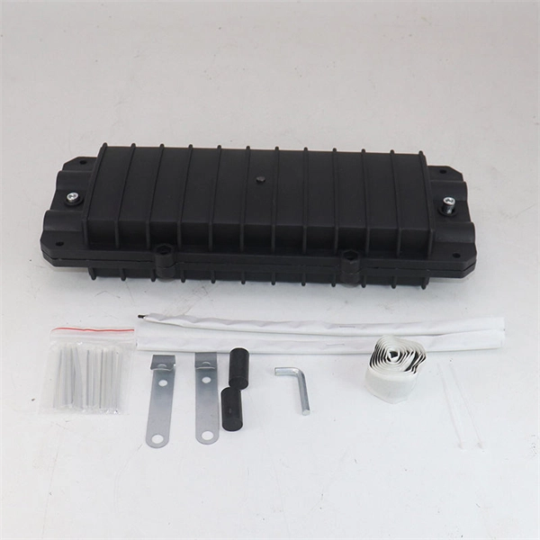
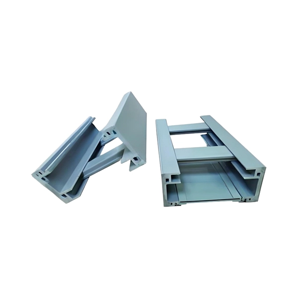
In modern FTTH architectures, the ODN is the physical fiber layer that distributes optical signals from the central office to end users. Operators consider ODN design as one of the most important factors affecting: Network coverage Optical loss performance Deployment cost. This passive layer is known as the Optical Distribution Network (ODN). Its role is to provide an optical transmission channel between the OLT and the ONU. The ODN network design is a physical facility that connects the communication room and user equipment, and is a key component. Short summary: The Optical Distribution Network (ODN) is the passive infrastructure linking the central office to the subscriber in FTTH. This guide delves into essential ODN components like splitters, distribution boxes, and ODFs, showcasing how Hainan ZTO Cable Co. It's the silent, robust highway that delivers blazing-fast Fiber-to-the-Home (FTTH) and 5G services. The maximum permissible optical power attenuation between OLT optical ports to ONT input is 28dB, which is by utilizing the so-called Class B optical network. At the heart of every Fiber-to-the-Home (FTTH) deployment lies the Optical Distribution Network (ODN) — a meticulously engineered passive infrastructure that enables operators to deliver massive bandwidth, low latency, and reliable service to millions of users. The ODN connects the Optical Line.
[PDF]

Fusion Splicer Settings – Must-Know for Fiber Technicians! 🔧 At D-TECH TRADING, we're demonstrating the essential Fusion Splicer settings that every fi. more. Auto Mode is the most intuitive and user-friendly splice mode. The fusion splicer automatically detects the fiber type, such as single-mode (SM), multimode (MM), or dispersion-shifted (DS) fibers, and adjusts parameters like arc power and heating time accordingly. Applications: Ideal for beginners. Page 1 Fusion Splicer 19R+/70R+ Quick Reference Guide Splice Operation • When splicing only standard SM fibers (ITU-T G. 652), “SM AUTO” mode is recommended. It also outlines instructions for keypad usage. st Instruction manual Fusion Splicer Please read this instruction manual carefully before operating the equipment. Adhere to all safety instructions and warnings contained in this manual. Keep this manual in a safe place. There is a change without a previous notice. We are not responsible for the. Fusion splicing is the bedrock of high-performance fiber optic networks, enabling seamless signal transmission through permanent, low-loss fiber joins. As a leading provider of fiber optic infrastructure, Weunion leverages cutting-edge tools like the AI9 and AI10 fusion splicers, paired with.
[PDF]