
Cable trays play a key part in keeping fire protection systems working. Here is what they do: They Make Safe Paths for Fire System Wires Cable trays are made from materials that resist fire. They can help stop fire from spreading. Recognize electrical cable tray misuse that can lead to electric shock and arc-flash/blast events and fires caused by overheating. The use and installation of cable trays is covered by legally enforceable OSHA regulations in 29 CFR 1910. 305(a)(3), or comparable standards promulgated by States. Scope: Firestopping for busway, cable trays, cables, and trunking passing through walls in enclosed electrical installations. Where cables pass through shafts, walls, slabs, or enter electrical panels or cabinets, openings shall be tightly sealed with firestopping materials in accordance with. Cable trays can be part of a planned cable management system to support, route, protect, and provide a pathway for cable systems. Power, low voltage control, data, or telecommunications wiring distribution systems can be used with cable trays. 1 This section applies to cable trays utilized to support and route low voltage cables (telecom, security, A/V). No fire alarm cables will be permitted to be installed in cable trays. If a fire starts, the tray protects the wires inside from flames and.
[PDF]
Distance relays, also known as impedance relay, differ in principle from other forms of protection in that their performance is not governed by the magnitude of the current or voltage in the protected circuit but rather on the ratio of these two quantities.OverviewIn, a protective relay is a device designed to trip a when a is detected. The first protective relays were electromagnetic devices, relying on coils operating on moving par. Electromechanical protective relays operate by either, or. Unlike switching type electromechanical with fixed and usually ill-defined operating voltage thresholds.
[PDF]

This manual describes the protection, automation, control, and monitoring functions of the SIPROTEC 5 devices. In order to protect technical infrastructures, systems, machines and networks against cyber threats, it is necessary to implement – and continuously maintain – a holistic, state-of-the-art. Busbar Differential Protection Definition: Busbar differential protection is a scheme that quickly isolates faults by comparing currents entering and leaving the busbar using Kirchoff's current law. Current Differential Protection: This protection method connects CT secondaries in parallel and. A busbar protection is a protection to protect busbars at short-circuits and earth-faults. In the “childhood” of electricity no separate protection was used for the busbars. With increasing short-circuit power in the network. SIPROTEC 7SS60 7SS60 is a numerical differential current protection for busbars. It is suitable for all voltage levels and can be adapted to a large variety of busbar configurations. Busbar protection is critical for the safe and reliable operation of a power system. Related Article: Busbar Protection Like any other faults. Bus bar protection scheme shall be provided for 220KV system where the sub-station layout arrangement is with 3-bus system (Main 1, Main 2 & Transfer Bus) or two bus system with Main bus with bus section breaker & Transfer bus.
[PDF]
Pilot-wire relaying is an adaptation of the principle of differential relaying to line protection and functions to provide high-speed clearing of the line for faults anywhere on the line. Pilots include wire pilot (us.
[PDF]

PC configuration software for Reyrolle products including Reydisp Manager 2, Reydisp Manager 1, and Reydisp Evolution. Doble RTS™ (RTS) is the premier protection testing software system for improving the work of testing relays and managing test records. Process consistency with power and flexibility set RTS software apart, and tremendous automation enables unmatched efficiency, accuracy and productivity. Apply your. Download documents, support information, software, video and audio content. IEC61850 Digital Substation Testing With 15 years experience in IEC61850 digital substation testing, KINGSINE portable relay testers are designed for comprehensive testing in both traditional and digital substations, including MU and IEC61850 compliant IEDs. Protection Relay Test Set/Kit KINGSINE. The commissioning of protection systems is an essential step to ensure the safety, reliability, and operational efficiency of electrical installations. In this context, the testing of protection relays and IEDs (Intelligent Electronic Devices) must be carried out with maximum precision, speed, and. A software designed to manage all aspects of protective relay testing using the Megger SMRT and FREJA models of relay testers. Facilitates steamlined and efficient relay protection testing through automation and relay modules. By using one of the over 400 relay templates with relay settings import. Portable at just 15 kg, the FREJA 300 is intended primarily for.
[PDF]

There are many types of protective relays, and each one is designed for a specific type of protection. Common types include overcurrent relay, differential relay, distance relay, earth fault relay, and under/over voltage relay. Protective Relay Definition: A protective relay is an automatic device that senses abnormal conditions in electrical circuits and triggers actions to isolate faults. HT panel protection relay. The HT power supply is received from GO switch and distributed to the. Provides protection, logic, and metering All-in-one solution. Combines protection, sensors, control power, and circuit breaker in a single package Typically added to a breaker close circuit to prevent accidental reclosure after a trip. Three fundamental components required for each circuit breaker. Its main purpose is to safeguard electrical equipment like transformers, generators, and transmission lines from damage due to. There are different types of relays available and each type is used based on the requirement. So this article discusses an overview of a protective relay or protection relay – working with applications.
[PDF]

This handbook covers the code of practice in protection circuitry including standard lead and device numbers, mode of connections at terminal strips, colour codes in multicore cables, dos and donts in execution. Also principles of various protective relays and schemes including special protection. Relay systems protect high-voltage equipment and transmission lines to ensure safe, stable systems. Ensuring that. lectrical work practices. See NFPA 70E in the USA, e conduit nut provi ource termination point. * NOTE: When connecting the control side of this device (#18 wires) to power line circuits, provide curre. 1/3HP@120V. The testing and verification of relay protection devices can be divided into four groups: Type tests are needed to prove that a protection relay meets the claimed specification and follows all relevant standards. Since the basic function of a protection relay is to correctly function under abnormal. Manual intended for personnel responsible for installing, commissioning and using VIP protection 400. The handbook for protection engineers includes guidelines on protective circuitry, protective relay principles, and testing procedures for switchgear and relays. It covers standard codes, wiring practices, and norms for protecting generators, transformers, and lines, and provides detailed.
[PDF]
Distance relays, also known as impedance relay, differ in principle from other forms of protection in that their performance is not governed by the magnitude of the current or voltage in the protected circuit but rather on the ratio of these two quantities.OverviewIn, a protective relay is a device designed to trip a when a is detected. The. Electromechanical protective relays operate by either, or. Unlike switching type electromechanical with fixed and usually ill-defined operating voltage thresholds. Electromechanical relays can be classified into several different types as follows: "Armature"-type relays have a pivoted lever supported on a hinge or knife-edge pivot, which carries a moving contact. These relays may.
[PDF]

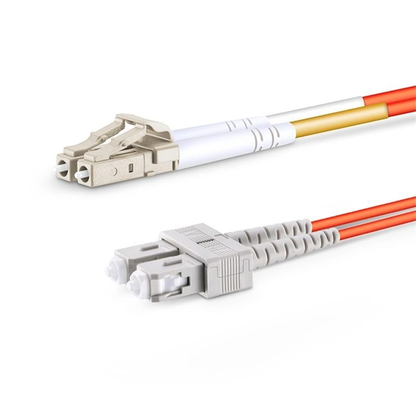
Optical cable lines lightning protection and strong current protection are achieved by avoiding, guiding or discharging them underground to prevent lightning and strong current from causing damage to the optical cable lines themselves, communication equipment and personnel. Since the lightning. Fiber optic cables have good protection performance, and the metal components of cable's insulation value is so high that lightning current can not enter the cable easily. However, because fiber optic cable has strengthened core, especially the direct-buried fiber optic cable has armoring layer. rocess approved by the American National Standards Institute. This process brings together volunteers representing varied viewpoints and i terests to achieve consensus on fire and other safety issues. While the NFPA administers the process and establishes rules to promote fairness in the. The Lightning Protection Institute is a nationwide not-for-profit organization founded in 1955 to promote lightning protection education, awareness, and safety. The lightning protection industry began in the United States when Benjamin Franklin postulated that lightning was electricity, and a metal. Defines lightning parameters (current waveform, peak values, charge transfer), threat classification, and damage/loss categories. Provides the risk assessment methodology.
[PDF]

Whether you're an electrician or a DIY enthusiast, this tutorial will help you understand the fundamentals of wiring a distribution box for a residential setup. The diagram of the distribution board's wiring shows exactly how each circuit is wired and connected. What is Distribution Board? Distribution board. A distribution box is the heart of any electrical system. It takes the incoming power and safely distributes it to different circuits throughout your building. Whether in a home or an industrial facility, this box keeps your electrical setup organized, functional, and efficient. However, the key to. In this guide, we will break down the key elements involved in connecting the main power supply to your home, providing a clear path for a successful setup. We will focus on the critical parts of the system, from basic components to step-by-step assembly procedures. It serves as a central hub for distributing electricity throughout a building, ensuring that power is delivered safely and efficiently to all the required locations.
[PDF]

This guide provides a complete breakdown of enclosure types, materials, certifications, temperature considerations, and installation insights to help engineers, designers, and safety professionals select enclosures that meet both operational and regulatory demands. Explosion-proof enclosures are used by such facilities to ensure the safe housing of electrical components that could cause a spark and ignite these gases in the atmosphere. What Is An Explosion Proof Box or Enclosure? They are a cast aluminum or iron box that can withstand a heavy-duty explosion. Explosion-proof and flameproof equipment is essential for safe operation in hazardous (classified) locations where flammable gases, vapors, or combustible dusts may be present. What Are Hazardous Area. Pepperl+Fuchs provides a specialized portfolio of Ex d (flameproof) and Ex tb (dust protection by enclosure) certified terminal boxes and junction boxes engineered for reliable use in explosion-hazardous areas. These sturdy solutions are certified according to global standards such as ATEX, IECEx. Blast-proof enclosures are protective devices designed to prevent the consequences of fires & explosions. Such structures are specially configured to be pressure vessels hence they can contain internal pressure without propagating it. Rather than stopping an explosion from occurring, the equipment safely manages it within a reinforced structure. Common protection methods include: These principles are.
[PDF]
We offer Meter Box, Panel & Panel & Surrounds at factory rates. Check out our online store for more Distribution Boards products. A meter box is a weatherproof enclosure that houses the electricity meter, main switch, and primary protection devices for a property. It sits at the boundary between the network supply and the consumer mains, giving the network distributor secure metering access while keeping circuit protection. AGM is leading wholesale electrical supplies store in Australia. Our best selling products are NSW Standard Meter Box (600 x 600 x 260mm), Panel & Surrounds 24x24x4 inch. An electric meter box is actually a critical part of any property's electrical system, as it provides secure and weatherproof housing for the electricity meter. Here at MJS Electrical Supplies, we stock a wide range of solutions, from a standard electrical meter box enclosure to a combined meter. Electrical distribution boards and meter boxes act as an enclosure for circuit protection and utility metering products. Electrical distribution boards offer personal protection, generous wiring room for commissioning and easy access to electrical equipment during maintenance. Our online. Can't find what you're looking for? Secure meter boxes for housing electricity meters. Designed for outdoor installation and compliant service entry setups. Buy Now and Pay Later with ZipMoney.
[PDF]
In this article, we will guide you through the step-by-step process of opening an electrical box safely and effectively. We will also highlight the necessary tools and materials you will need to complete the task. The electrical service panel, commonly known as the breaker box, acts as the central distribution hub for all electrical power entering a home. This metal enclosure receives high-voltage current from the utility company and safely divides it into various circuits that supply power to lights. So, before we dive into the discussion, here's a list of tools that you must have. Electric Drill/Screwdriver 2. Personal Protective Equipment Step 1. Clear your working area Step 2. Estimate the cover's weight Step 4. It is responsible for controlling and distributing the electrical current throughout your house, ensuring the safety and efficiency of your electrical appliances and devices. This article details the process of installing them, which helps you comprehend distribution boxes. An electrical panel box, also known as a breaker box or a distribution board, is a crucial component of any electrical system. Whether you're a seasoned DIY enthusiast or simply looking to understand the procedure, this guide will provide a clear roadmap to ensure a smooth and safe transition. Let's embark on this.
[PDF]
See a sample diagram and download it in different formats. Electrical enclosure sizes are not universal, but most manufacturers follow common size families. This guide explains typical wall-mount and floor-standing dimensions, how to read catalog sizes, and how to choose the right enclosure size for your layout. What Are Electrical Box Dimensions? Electrical box dimensions typically refer to: Correct dimensions ensure:. Solid rubber (construction) distribution box suitable for construction and industry according to EN-61439-4. Available from stock. The only one in the Benelux with a Dekra quality mark. Distribution boxes 32 Amp. Explorez notre Guide Complet du RGIE : Schémas Électriques, Conseils de Conformité, Assistance Gratuite pour la Sécurité et la Mise aux Normes des Installations, et Accès Direct aux Électriciens et Agences Agréées. Discover easy access to the Belgian Electrical Regulations resources, structured. Sheet Electrical: Electricity symbols for floor plans (based on Belgium regulations). Learn more about these objects, how they can be added to your Dia toolbox and how you can draw your diagrams with them. Boxes distribute low currents in an area equipped with 1 to 12 RJ 45 sockets. They centralise connections to ensure flexibility and that the installation is up to date. Area boxes can be installed in technical flooring or in false ceilings.
[PDF]

The modern electric power transmission, control, and distribution network demands precision, reliability, and advanced data analytics for each step in its operation. As a Relay Protection Engineer, your work in relay testing and commissioning is critical to ensuring system safety and continuity. In. The testing and verification of protection devices and arrangements introduces a number of issues. This happens because the main function of protection devices is related to operation under fault conditions so these devices cannot be tested under normal operating conditions. Protection relays are critical for detecting faults, initiating protective actions, and isolating faulty sections of the. Relay systems protect high-voltage equipment and transmission lines to ensure safe, stable systems. Although failure of a protective relay system may have severe local or regional impacts, most protective relay systems are not required to operate to prove they are in working order. Ensuring that. The strategies available to remove these risks are many, but all involve some kind of testing at site. Modern power systems are becoming increasingly complex, with growing demand, integration of renewable energy, and rising expectations for reliability and safety. In this environment, protection relays serve as the guardians of.
[PDF]


