A 4 Core Optical Cable is a fiber optic cable that contains four individual optical fibers within a single protective outer jacket. Each fiber is capable of independent data transmission. A TOSLINK optical fiber cable with a clear jacket. These cables are used mainly for digital audio connections between devices. A fiber-optic cable, also known as an optical-fiber cable, is an assembly similar to an electrical cable but containing one or more optical fibers that are used to carry. This guide covers everything you need to know about 4 core fiber, including its internal structure, TIA standard color coding, and how to choose the right type. They are ideal for long-distance communication and. But generally, the cable core, strength member and outer sheath together make a fiber optic cable. It transmits electricity or information from one place to another. These fibers are used to transmit data as light signals, offering high-speed data transfer capabilities over long distances with minimal loss. Fiber optic cables are crucial.
[PDF]
Underground cables are pulled in conduit that is buried underground, usually 1-1. 2 meters (3-4 feet) deep to reduce the likelihood of accidentally being dug up. In extreme cold climates, cables may need to be buried at greater depths where there temperatures are colder and frost penetrates to. Underground cable is placed into ducts which are being built below the ground surface. In urban areas where space for telecommunications cable is limited, it needs to be used more efficiently. In underground installation, the conduit provides protection from both physical and environmental abuse. ed loose tube cable is 600 lbF (2,700 Newtons). Refer to the cable specification sheet or t ion) and “ Installed” (after installation). The following formulas may be used to determine general guidelines for installing Corning Optical Communications fiber optic cable; however, refer to the cable. The Fiber Optic Association, Inc. (FOA) was founded in 1995 to help develop the workforce to build the fiber optic networks to support a rapid expansion in communications and the Internet. It also facilitates cable management and ease of maintenance. With these assemblies we mention in this article, the widest point of. This document covers cable placing in conduit, innerduct, handholes, and manhole structures. The innerduct may be direct buried or placed in larger diameter conduits. This document covers conventional cable placing techniques.
[PDF]
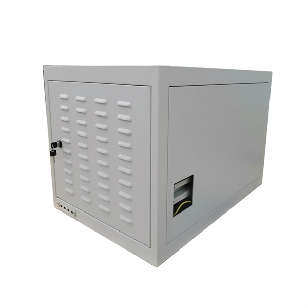
In short, the terminal box is the last structured node of the Fiber Optic System before service touches the subscriber. A typical PON topology (GPON, XGS-PON, or 25G PON) flows OLT → fiber distribution hub → passive splitters → distribution/drop fibers → premises. The terminal box sits at the. In broadband optical fiber access network, we often see the all kinds of fiber box such as fiber cabinet, fiber optic distribution box, fiber optic terminal box, multimedia box, and customer box. What is the difference between these fiber boxes. Let's look at the position of various fiber box in. A fiber cable (drop) is run from a nearby terminal that could be either a pole or an underground box) to your home. A small box on the outside of your home called a NID is installed and the fiber is coiled in there and connected to a fiber that runs into the home. The fiber is connected to an. Fiber Distribution Boxes (FDBs) are critical components in modern telecommunications infrastructure, particularly in fiber optic networks. They function as junction points that manage, protect, terminate, and distribute fiber optic cables, ensuring efficient data transmission between different. Aerial Service Drop: A cable coming from a pole to your house, connected at a small box called an MST. Underground Service Drop: A cable buried underground, either in a new tube or an existing pipe. Network Interface Device (NID): A box where the internet service meets your home's wiring.
[PDF]
Underground fiber optic cable carries the vast majority of the world's internet traffic, phone calls, and digital data. These cables are buried beneath streets, sidewalks, and rural land to connect homes, businesses, data centers, military installations, and city infrastructure. While the glass. Underground fiber optic cable is designed for direct burial or conduit installation and is widely used in FTTH networks, backbone infrastructure, and industrial communication systems. This guide explains underground fiber optic cable types, installation methods, burial depth, and practical. One of the key components driving this connectivity is underground fiber optic cable. It has been increasingly used in telecommunications networks around the world. Introduction of The Buried Fiber Optic Cable Fiber optic cables have revolutionized the way we transmit data, offering unparalleled speeds and reliability.
[PDF]
The NEC explicitly states that conductive optical fiber cables are not allowed to occupy the same cable tray or raceway as the aforementioned electrical conductors. The key difference here is safety. Nonconductive Optical Fiber Cables: These are typically indoor/outdoor rated fiber cables. This includes conductors for electric light, power, Class 1, non-power-limited. Maintaining proper separation between power, data, and limited energy cabling is foundational to system performance, safety, and code compliance. Separation isn't just an EMI precaution — it protects signaling, reduces rework, and ensures pathways meet inspection expectations across risers. Informational Note: 1 method of defining a cable that is low-smoke producing cable and fire-resistant cable is that the cable exhibits a maximum peak optical density of 0. 50 or less, an average optical density of 0. 52 m) or less when tested. Optical fiber cables shall be permitted to be installed in metal or listed nonmetallic cable tray systems. The previous requirements of 770. Most fiber cables are non-conductive so they can be placed alongside high voltage cables without any special insulation. cable installation must meet the NEC and local building code. Properly fiber rated fiber cables can use the same cable.
[PDF]
In September 2012, NTT Japan demonstrated a single fiber cable that was able to transfer 1 per second (10 bits/s) over a distance of 50 kilometers. Although larger cables are available, the highest strand-count single-mode fiber cable commonly manufactured is the 864-count, consisting of 36 ribbons each containing 24 strands of fiber. These high fiber count cables are used in, and as distribution cables in and networks.
[PDF]
Search results of Top 20 Cabling and Fibre Optics Companies in Myanmar, near me. Listings are verified with accurate business information. Last updated May 2026 We found 20 listings in Myanmar No 25/26, Bayint Naung Main Road, Block (3), Hlaing Township, Yangon, Myanmar Nat Sin Street #102, Kyee Myin Dine Tsp, Yangon, Myanmar No. 71, Upper Pazundaung Road, 6th. Yadanarbon Fibre Co., Ltd was established in 2009 as the pioneer of fiber optic cable manufacturer in Myanmar. Our services include project-based. Founded in 1968, Anhui Telecom Dvices Trade &., Ltd is located in Hefei City. The company's buiness involved in China Telecom, China Mobile, China uNICOM Image to Text Copyright © 2015-2026 listcompany. List of Optical Fiber Cable Companies in Myanmar. Trade Alerts are FREE updates on topics such as trending hot products, buying requests and supplier information - sent directly to your email inbox! Alibaba offers 23 Fiber Optic Cable Myanmar Suppliers, and Fiber Optic Cable Myanmar Manufacturers, Distributors, Factories, Companies. EMIN Indonesia. Merry Mesh Network Integration Company Limited was founded in 2007 with the aim to secure projects in Myanmar as well as to provide user-friendly turnkey solutions for our customers. We provide design, installation, servicing and maintaining the equipments according to our customers' requirements.
[PDF]
The first in-fiber Bragg grating was demonstrated by in 1978. Initially, the gratings were fabricated using a visible laser propagating along the fiber core. In 1989, Gerald Meltz and colleagues demonstrated the much more flexible transverse holographic inscription technique where the laser illumination came from the side of the fiber. This technique uses the interference pattern of ultraviolet laser light to create the periodic structure of the fiber Bragg grating.
[PDF]
Fiber optic patch panels are enclosures that act as a distribution hub for fiber cable. A bulk (multi-strand) fiber cable enters the patch panel and then each fiber strand is separated into individual strands or pairs of strands. Fiber optic communications has been a rapidly expanding industry for the last 20 years. In its early years, it was mainly used for backhaul communications between large ISP's. But now fiber is widely used and can be found almost anywhere. It's probably in your ofice, on the telephone poles outside. A fiber patch panel is a mounted enclosure—either rack-mounted or wall-mounted—used to terminate, manage, and interconnect multiple fiber optic cables. It acts as a hub for organizing splices and patch cords, streamlining fiber management and preserving signal integrity. It provides a central point where incoming fiber cables can be connected to outgoing patch cords, making the network structured, accessible, and easy to maintain. This makes it easier to alter or troubleshoot the connections as they act as a central point where. Fiber patch panels play an increasingly important role in the optical fiber network due to the widespread use of high-density cabling systems in data centers. They are available in various fiber connector types, such as LC patch panel, SC patch panel and MTP patch panel. This article explores the structure, functionality, types, and benefits of fiber optic patch panels. What's the Fiber Optic Patch.
[PDF]
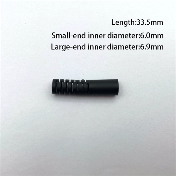
This guide covers everything: what fiber optic pigtails are, how they differ from patch cords, which connector and polish type to specify, how to choose between mechanical and fusion splicing, and the real-world applications where pigtails are the right call. Executive Summary: A fiber optic pigtail is one of the most commonly specified yet least understood components in structured cabling. Get the wrong connector type, the wrong polish, or skip proper fusion splicing technique—and you're looking at elevated signal loss, increased back reflection, and a. In this guide, we'll break down what fiber optic pigtails are, how they work, their types, and how to choose the right one for your application. What Is a Fiber Optic Pigtail? A fiber optic pigtail is a short optical fiber cable that has a connector on one end and an exposed (unterminated) fiber on. When designing or maintaining fiber optic networks, understanding fiber pigtail specifications and fiber pigtail types is crucial for optimal performance and reliability. At JUNPU, we specialize in manufacturing high-quality fiber optic components that meet the most demanding industrial standards. By the end, you will have a comprehensive understanding of why pigtails deserve a place in every fiber deployment toolkit. They are available separately or in kits for ease of installation and ordering. Simplex or multifiber pigtails are available. We also provide a full set of customized services, such as fiber counts.
[PDF]

A typical fiber optic splice enclosure consists of several key components that work together to protect and organize the fiber splices. Standard enclosures contain: 1) Housing, 2) Cable fixation clamps, 3) Splice trays, 4) Sealing system. A splice box (also known as splice distributor) is a housing in which fiber optic cables begin or end. Fiber optics are fanned out in splice boxes that are situated at the end of fiber optic transmission paths. Optical cable joint box The optical cable joint box permanently connects two optical cables together and has a joint part for protecting components. The optical cable connection part, that is, the optical cable joint, is the part where the. An optical cable split fiber box, also known as a fiber distribution box or fiber optic splice closure, is a device used to terminate, splice, and distribute optical fibers. In this response, we will focus on the. This guide optimizes the original text by delving deeper into the three pillars of fiber network longevity: the impact of splicing technology, the strategic selection of splice boxes, and the essential maintenance protocols needed to ensure sustained, high-speed functionality. Fibre optic cables are manufactured in standardized lengths –.
[PDF]

While optical power meters are the primary power measurement instrument, optical loss test sets (OLTSs) and optical time domain reflectometers (OTDRs) also measure power in testing loss. TIA standard test FOTP-95 covers the measurement of optical power. This measurement is the basis for loss measurements as well as the power from a source or presented at a receiver. Typically both transmitters and receivers have receptacles for fiber optic connectors, so measuring the. You need a power meter to measure power in a fiber optic system; most power meters come with a screw-on-adapter that matches the connector being tested and a little aid from the network electronics to turn on the transmitter. During the measurement of power, the meter must be set to the proper. Fluke Networks sets the standard in network testing with its advanced range of fiber optic power meters and fault locators, designed to ensure the highest precision in fiber optic meter readings and power evaluations. This is measured in decibels (dB). Splitters, fusion splices, connectors and. To use a power meter for fiber optic testing, always clean connectors first with lint-free wipes or click-to-clean tools. Select the correct wavelength and set your reference. Consistent procedures ensure accuracy.
[PDF]
Fiber optic color coding is an essential part of managing and working with fiber optic cables and components. The TIA-598-D standard defines a standardized color-coding system that engineers and technicians rely on to identify different types of fiber optic cables, connectors, and. Understanding fiber‑optic color codes is essential for any technician tasked with installing, maintaining, or troubleshooting modern fiber networks. But with thousands of fibers in a single cable, color coding is your universal translator. Without it, you'd be lost in a spaghetti mess. Fiber optic color knowledge is crucial for anyone working in telecommunications, networking, or data management. Yet, correctly identifying and sorting these cables is paramount in. You'll learn how to identify single-mode vs. multimode at a glance, trace individual strands in a 144-fiber bundle, and avoid the critical error of mixing connector types. In fiber optics, color isn't for decoration; it's a critical safety and efficiency tool. This standardized fiber optic color coding system helps prevent costly connection errors while dramatically.
[PDF]
Return-to-zero (RZ or RTZ) describes a line code used in telecommunicationssignals in which the signal drops (returns) to zero between pulses. This takes place even if a number of consecutive 0s or 1s occur in the signal. The signal is self-clocking. In digital communication systems, line encoding schemes are crucial for representing binary data efficiently and reliably. RZ (Return-to-Zero), NRZ (Non-Return-to-Zero), CRZ (Chirped Return-to-Zero), and CSRZ (Carrier-Suppressed Return-to-Zero) are distinct line coding methods, each with its own. Abstract—Analytical formulas for the power spectra of return-to-zero (RZ) optical signals generated by Mach–Zehnder (MZ) modulators are derived. This means that a separate clock does not need. The experiment aim of this experiment is to analyze the operation of Non-Return to Zero(NRZ), Return to Zero(RZ) and Pulse ration encoders and decoders. The setup created in OptSim is shown below: Each link.
[PDF]
The vertical clearance for overhead fiber optic lines above the highway must be a minimum of 18 feet. org The Fiber Optic Association, Inc. (FOA) was founded in 1995 to help develop the workforce to build the fiber optic networks to support a rapid expansion in communications and the Internet. The charter of the FOA was to promote professionalism. 4. FO-VC2 JOINT USE - VERICAL MIDSPAN CLEARANCES 48. FO-GB GROUNDING AND BONDING 49. FO-RI JOINT USE RISER. cations, security, control and similar purposes. It defines a minimum leve e fiber optic cabling extends between buildings. Although the standard covers premises installations, many of the provisions included here ar SI/ NFPA 70, the National Electrical Code (NEC). It is the responsibility of users. safety glasses, harness when more than 4' off gro house and pull line out to the ap g, J-hooks, drop hangers, and zip ties whe raight-line poles and 2 J-hooks when mak, around every 3rd pole, and at the last pole drop hits. For example, on a ead for mast attachments and P-hook for eve the. The plate RC. It should be plated for each cable once per station, not per foot. Field conditions will vary, so the actual location. Fiber optic cable installed in conduit shall be in accordance with the following: 132. No more than two 90 degree changes in direction per cable pull. Circuitous pulls and pulls exceeding 1000' (300 m) shall be made by back feeding or center feeding of cable.
[PDF]