The WannaCry ransomware attack was a worldwide cyberattack in May 2017 by the WannaCry ransomware cryptoworm, which targeted computers running the Microsoft Windows operating system by encrypting data and demanding ransom payments in the form of bitcoin cryptocurrency. It was propagated using EternalBlue, an exploit developed by the United States National Security Agen. DescriptionWannaCry is a , which targets computers running the by encrypting (locking) data and demanding ransom payments in the. The attack began on Friday, 12 May 2017, with evidence pointing to an initial infection in Asia at 07:44 UTC. The initial infection was likely through an exposed SMB port, rather than as initially ass. Linguistic analysis of the ransom notes suggested the authors were likely fluent in Chinese and proficient in English, as the versions of the notes in those languages appeared to be human-written while the rest seeme. The ransomware campaign was unprecedented in scale according to, which estimates that around 200,000 computers were infected across 150 countries. According to, the four mo.
[PDF]

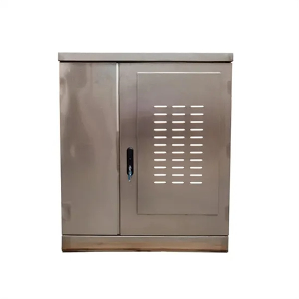
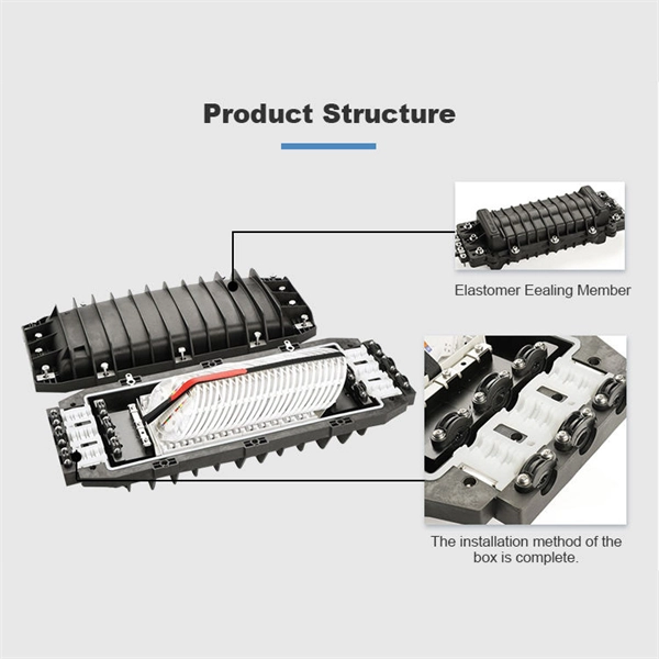
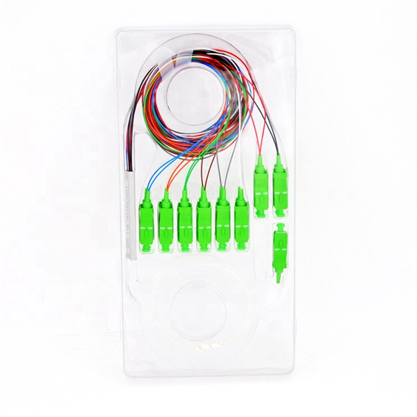
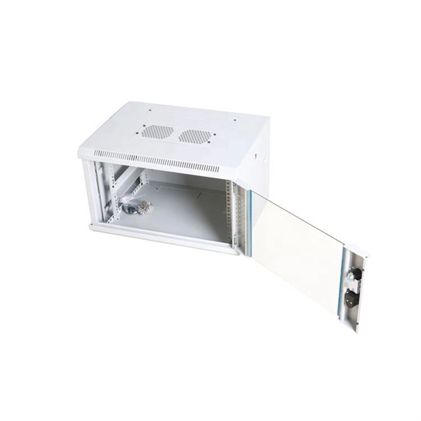
With protective doors, dust-proof 2). Suitable for many types of modules, used in cabling work area subsystem 3). Embedded type surface, easy for installation and removal 4). Available for fiber optic SC simplex or LC duplex and can be used in both surface mounted. 1). This termination box supports 0. 0mm pigtails and 2x3mm indoor drop cables. Discover the Welink FTB-1005: a high-quality 1 Core Fiber Optic Outlet for FTTH. RoHS certified, compact, durable, and easy to install. Compact Design: Space-saving footprint (86x86mm) ideal for residential and office wall mounting. Splice Protection: Integrated tray securely holds fusion. FTTH Terminal box is a compact fiber terminal for use at the final fiber termination point in the customer premises. It provides mechanical protection and managed fiber control in an attractive format suitable for use inside customer premises, A variety of possible fiber termination techniques are. 1 Core Fiber Optic Desk Terminal Box for SC, FC Adapter, Patch Cord or Pigtail Description: 1). It provides a secure and convenient location for fiber optic splicing, connecting the drop cable and the passive optical equipment of the optical network. protection and management for the FTTx network building. Features: Scope of application 3. Specification: Applications: 1 Core Fiber Optic Terminal Box is used as a termination point for the feeder cable to connect with drop cable in FTTx communication network.
[PDF]
F port is FastEthernet interface and fast Ethernet port, also known as 100M port. It is mainly used to connect switches or computers. When selecting or configuring a network switch, you often encounter ports labeled G, F, E, and S. Understanding the differences between these port types is essential for proper network design, cable selection, and optical module compatibility. Below, we break down each port type in detail. You can use commands to set bandwidth. This article will focus on the four common interfaces: G port, F port, E port, and S port to facilitate understanding before installation. S port The meaning of Serial interface is also called high-speed. S port is fully called serial interface, also known as high-speed asynchronous serial port. E port It is the Ethernet interface. Each Fibre Channel port can be used as a downlink (c onnected to a server) or as an uplink (connected to the data center SAN network).
[PDF]

Are SFP modules universal? No — and using the wrong one can lead to errors or no connection at all. But with the right information and a trusted supplier, you can avoid compatibility issues and save money. Q1: Can I use a third-party SFP module in my Cisco switch?. SFP (Small Form-factor Pluggable) is a compact, hot-pluggable network interface module used to connect network devices (switches, routers, firewalls) to fiber optic or copper cables. It helps your device connect to a fibre optic or copper cable — like a SIM card for your phone, but for your network. SFPs are used for different network types and speeds. Switch optical modules, which convert electrical signals to optical signals and vice – versa, and optical interfaces, which serve as the physical connection points, play a pivotal role in determining the speed, distance, and reliability of data transmission. Transceiver compatibility is a key concern in enterprise network deployments. Can an SFP. Every network engineer runs into it: the optical transceiver that should work, but doesn't. First, there's form factor—the SFP you used last year won't fit the QSFP-DD ports your new switches need. Then protocols and speeds complicate things. An optic that handles Ethernet might fail entirely on a.
[PDF]

The typical thickness of a glass core can range anywhere from 8-10 um (microns) for single-mode and 62. 5-50 um for multimode; these core sizes are the most prevalent ones utilized in the telecommunications industry. The core of a conventional optical fiber is the part of the fiber that guides the light. It is a cylinder of glass or plastic that runs along the fiber's length. The core is surrounded by a medium with a lower index of refraction, typically a cladding of a different glass, or plastic. The light is transported along the optical fiber via its smallest and most crucial component, which is called the core. However, they are composed of many components, each constructed from advanced materials to guarantee the quick and reliable transmission of data. So, let's break it down! The core is the primary part of a Fiber optic cable. It's responsible for. The 8 Core Multimode Outdoor Fiber Optic Cable is designed for high-performance data transmission in various outdoor environments, making it an ideal choice for telecommunications, networking, and data center applications. We supply single mode GYTS fiber optical cable and multimode GYTS fiber optic cable, fiber strand from 2 cores to 432 cores. A related GYTA type cable is available. This advanced cabling solution allows fast, secure data transfer and telecom over long distances. Understanding the components within a fiber optic cable enables.
[PDF]
With up to 48 10 GE downlinks and 40/100 GE uplinks, the S6730‑H series supports bandwidth-hungry access and spine layers—perfect for Wi‑Fi 6 APs, 4K/8K video, and virtualization workloads. Based on Huawei's VRP OS, the series delivers OSPF, BGP, RIPng, IS‑IS, VRRP, and. This document provides campus networks typical configuration examples and feature typical configuration examples. "Campus Networks Typical Configuration Examples" provides typical campus network networking modes and a variety of deployment examples. Positioned perfectly as an Aggregation Switch or Core Switch, the S6730‑H delivers scalability, security, and cost-effectiveness for modern digital. The S5730-SI series switches are next-generation standard gigabit Layer 3 Ethernet switches. They can be used as access or aggregation switches on a campus network or as access switches in a data center. It also provides enhanced Layer 3 features and mature IPv6 features. eKitEngine S530 switches can be use in various scenarios. The S3700 utilizes cutting-edge hardware and Huawei Versatile Routing Platform (VRP) software to provide high-performance access and aggregation to an enterprise campus network.
[PDF]

There are 48 bicolor LEDs (green/amber) for the first 48 SFP+ ports and 16 tricolor LEDs (green/amber/white) for the SFP-DD ports. The last set of LEDs pulse once in white before indicating the FC port status in green or amber. When it blinks white twice, it shows the status of the second port of the SFP-DD. The port status LEDs for the FC ports are arranged left and right to correspond to the upper and lower ports respectively in each pair. LEDs on the port side of the switch Table 1. LEDs on Cisco Catalyst 9500 Series Switches 1 Available only on switches with 10G ports. System LED Indicator System is not operational. System is operating normally. As a group or individually, the LEDs show information about the switch and about the ports Preventing Overload - Each port that provides PoE has a maximum power it can deliver. Three LEDs are used on each port. Ports on the Cisco Catalyst switch do not have LEDs. Not the question you're searching for? Each. Number of LEDs per port - Ports that cannot be split; for example, 1G ports must have 1 LED per port. Location - A port LED should be placed right above the.
[PDF]
Step 3 Remove the cables or optical modules from the old card. Press the two green locking clips in the middle of the card to eject the ejector levers. Turn the ejector levers outward and slowly pull the card out. Place the replaced. Unplug the optical fibers from the optical module before removing it. Install or remove optical fibers carefully to avoid damaging the fiber connectors. If an optical module cannot be completely inserted into an optical. Page 7 Optical port USB storage device Wi-Fi terminal 1. Wear an ESD wrist strap or ESD gloves when replacing the optical module. Therefore, replace an optical module only when you confirm.
[PDF]

The SFP port is a built-in optical port of a Gigabit Ethernet switch, so it cannot be directly connected with a twisted pair or a jumper. It needs to be connected to an optical module first, and then it can be transmitted with an optical fiber patch cord. This chapter describes how to configure Gigabit Ethernet switching on the Catalyst enterprise LAN switches. Note For complete syntax and. Si ce produit est vendu au Canada, vous pouvez accéder à ce document en français canadien à https://www. com/support/download/. The RJ45 port is for copper cable. al installation guidelines and recommended procedures. To deploy this switch effectively and ensure trouble-free operation it is recommended to first read the relevant sections in this guide so rk administ tors and support personnel that install, e is based h relevant specif tions and. This command is configured in layer-2 interface configuration mode. The optical interface speed is fixed. The optical/electric port cannot support the gigabit and full-duplex at the same time. The ordinary TX port does not. The guidelines for configuring speed on QFX5100-48T switch are as follows: If the speed on the switch is set to 10-Gbps or auto, the switch advertises all the speeds. If you have configured the speed to 100 Mbps.
[PDF]
Optix America's WRX600 clad alignment fusion splicer: compact, precise, and reliable. Includes complete kit with advanced features. Order Now!. The FSP200 touchscreen optical fusion splicer uses core alignment technology, which allows the technician to reliably fuse fiber optic cables with low splice losses in as little time as seven seconds. Precision Rated Optics' PRO-730 Core Alignment Fusion Splicer Kit is a core alignment fusion splicer designed for use in most of today's fiber optic deployments. Whether your. Single Fusion Core Alignment Fusion Splicers are some of the most advanced Fiber Optic Fusion Splicers on the market today. Advanced servos inside these magnificent machines match the X and Y axis of the core of the fiber for the highest quality, lowest lost fusion splice. With industry-leading splice speed and support for G. 654E ultra-low-loss fiber, the C10S V2 delivers the precision and.
[PDF]

Learn how to splice fiber optic cable using fusion splicing with this complete step-by-step guide. Includes tools, best practices, loss standards (ITU-T G. 652), cost analysis, and FAQs for network engineers and installers. Splicing fiber optic cable is an extremely important phase for making dependable, high-speed communication infrastructures. Regardless of the type of fiber network you're deploying, be it for telecom, enterprise data centers, or smart city infrastructure, fusion splicing provides the benefits of. Proper connection of fiber optic cables is essential to harness these benefits fully, as even minor errors can lead to significant performance issues like signal loss. This article will guide you through the necessary tools, materials, and methods on how to connect fiber optic cables effectively. Previous video we explain how to do splicing of fibers optic cable in joint closure. this video are showing how to arrange sleeves in the cable tray and arrangement of fibers. Before connecting any fiber cable, you need to assemble the proper preparation tools: With the right tools in hand, follow these key steps to achieve reliable fiber connections: 1. Strip and Clean Fiber Ends. Fiber optic internet delivers blazing-fast speeds and reliable connectivity, making it a top choice for modern homes and businesses. However, setting up a fiber optic connection to your router can seem daunting if you're unfamiliar with the process.
[PDF]

Download new and previously released drivers including support software, bios, utilities, firmware and patches for Intel products. trol I/O is desired. The Q-SYS Core 24f satisfies a broad spectrum of application needs from meeting room environments, conferencing systems, retail establishments, houses of worship, judicial environments, education institutions and other general purpose pro essing applications. A Core 24f may be. That change is why correct leads and connections matter for system stability and lifespan. Please sign in or register for an Intel account. Automatically update your drivers and software Use this tool to identify your products and get driver and. Purpose: This connector serves as the main junction, transmitting essential electrical currents from the supply unit to the motherboard. Design: It features a distinct arrangement of multiple connectors, each designated for specific functions, ensuring balanced and stable power distribution. Product replacement Get replacements and find substitutions for discontinued Schneider Electric products. Where to buy Search our network of verified distributors with over 15,000 sales outlets. Communications bus and supply power terminal blocks, functions, ratings, requirements, and cables provides information about the functions, ratings, and requirements for the communication bus and supply power terminals; and guidelines for wire sizes, cable types, and cable lengths when wiring the.
[PDF]
The MALD-37059 is a four channel CDR with a directly modulated laser (DML) driver for use as a transmit device in optical modules. EML: Separates the light generation function from the modulation function. It uses an external modulator to shape the signal, which improves performance in high-speed, long-distance transmission. On paper, the difference looks small. In real deployments, it can completely change the behavior of a. DML refers to a directly modulated laser. This laser is also called a distributed-feedback laser diode (DFB) since it uses a distributed feedback structure. There are two modulation techniques for optical modules, DML and EML, which are briefly introduced in this article. The optical signal transmitted in the optical fiber is not constant, but is modulated, intensity changes in the optical signal, the following is a description of the characteristics. Optical transceivers primarily adopt two mainstream modulation technologies: DML and EML. This article provides a brief introduction to both. Basic Principle of Optical Transceivers The core function of an optical transceiver is to achieve optical-electrical conversion. Ethernet layer: business as usual. 400GE or 4x100GE breakout Optical channel:.
[PDF]
In 1880, and his assistant created a very early precursor to fiber-optic communications, the, at Bell's newly established in. Bell considered it his most important invention. The device allowed for the of sound on a beam of light. On June 3, 1880, Bell conducted the world's first wireless transmission between two buildings, some 213 meters apart. Due to its use of an atmospher.
[PDF]

The BA-1 device produces step attenuation of a laser beam to a maximum of about 44 dB . With the preattenuator beam splitter, denoted by SI, this range can be extended as much as another 3 0 dB. The various low level beams generated by BA-1 can be used for detector respon-sivity and. Danielson, B. (1977), Measurement procedures for the optical beam splitter attenuation device BA-1:,, National Institute of Standards and Technology, Gaithersburg, MD, , https://doi. 77-858 (Accessed February 10, 2025) If you have any questions about this publication or. Beam splitters are optical devices that play a crucial role in various scientific and industrial applications. They are used to divide a beam of light into two or more separate beams. NBS interagency report is a publication of the U. The papers are in the public domain and are not subject to copyright in the United States. The BA-1 system is designed for use at. The attenuation ratios of these wavelengths are calculated values. An analysis of the estimated uncertainties is. SPLITTER ATTENUATION DEVICE BA-1 B. Danielson Measurer::ent procedures are described for the step attenuation of laser bearriS up to 44 dB using a specially constructed attenua- tor box (BA-1). a laser beam) into two (or sometimes more) beams, which may or may not have the same optical power (radiant flux).
[PDF]