You can buy a manufactured 90 degree bend or make one on a cable tray bending machine but in this video I show you how to make one using a metal bar. Students trading aid on how best to put an internal 90 degrees bend in steel cable tray. more. The bends, tees, crosses, risers and reducers of wire mesh cable tray can be easily and quickly made live at the project by using a bolt cutter. Since the jaws of the bolt cutter drags a layer of zinc across the cut end and forms a protective layer. When a wire cable tray is cut, the fact that a. Choose a cable tray fitting with a radius equal to or greater than your calculated minimum. Common standards are 300, 450, 600, and 900 mm. How to calculate cable tray bends? Calculate the minimum required bend radius by multiplying the cable's outside diameter by its bending factor (e., 10x for. Use this guide to learn the most effective installation practices when installing Cablofil tray. Each example of bends and tee's clearly illustrate proper tray cutting combined with recommended usage of Cablofil accessories. This involves a few essential steps to ensure a successful bending process. The first step in preparing the. ns and Cross Joints. These arrangements can be created by using our standard cable tray sections and removing specific pieces as directed using the Cutter tool (WR-TRAYCTR65), and then bending and securing the tray pieces together using Couplers (WR-CPLKK34), Corner Strength Bars (WR-CNRSBAR-EZ).
[PDF]
This calculator determines the maximum number of cables that can be safely housed within a cable tray based on its dimensions and the cross-sectional area of the cables. Proper tray and ladder sizing ensures safe, efficient, and maintainable electrical installations in all engineering applications. IEC 61537 and IEC 60364 require evaluating tray dimensions based on cable quantity, type, and layout configuration. Below are industry-standard tray and ladder. A Cable Tray Capacity Calculator is an essential tool for electrical engineers, contractors, and project managers involved in the installation and management of electrical cables. Calculate Cable Cable Calculate the cross-sectional area of a single cable, then multiply by the total number of cables. For mixed cables, sum the areas of all individual cables. Plan cable trays with fill, weight, spacing, and growth checks. Compare standard sizes quickly now. Export clear results for safer electrical layouts and upgrades. The following formula is used to calculate the cable tray capacity: Variables: To calculate the cable tray capacity, multiply the width and height of the cable. This is best exhibited by cable tray width calculations for three different examples of single conductor cables in ladder or ventilated trough cable tray that are permitted by NEC Article 318. The examples are based on installations that contain 12 - 500 kcmil cables (four - three phase - 480 volt.
[PDF]

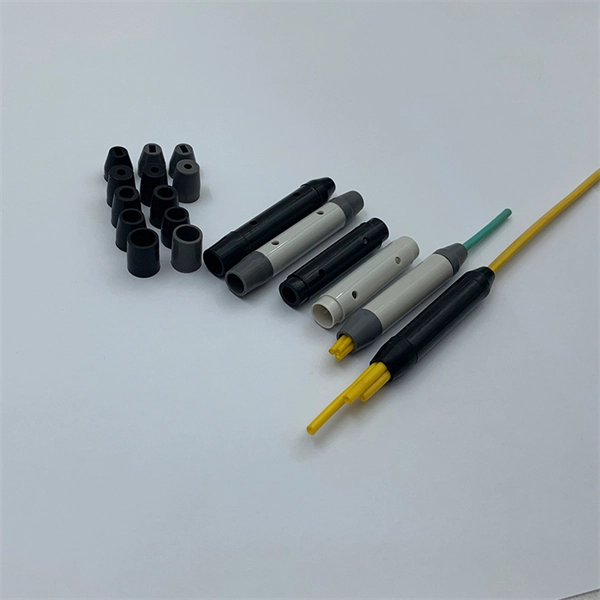
An Optical Splitter, also known as a beam splitter, is a passive optical device that divides a single input optical signal into two or more output signals. Conversely, it can also combine multiple signals into one. Knowing the difference between a splitter and an optical coupler helps you build better networks. You make your network work better when you pick the right device for each job. You can connect many users to one port with 1:n or 2:n splitters. By dividing a single optical signal from a central Optical Line Terminal (OLT) into multiple outputs for Optical Network Terminals (ONTs) at users' homes, splitters eliminate the need for dedicated fibers to each residence—slashing infrastructure costs while scaling network reach. This guide. In a Passive Optical Network (PON), a single optical fiber carries massive amounts of data using light. Signal Input: The fiber splitter receives the optical signal from the upstream network node and enters the splitter through the input fiber. Signal Distribution: Inside the splitter, according to the design structure and different. Splitters are passive optical devices that divide or combine optical signals, and they come in various types, including power splitters, uneven splitters, and wavelength-division multiplexing (WDM) splitters. Each type serves specific applications, enabling efficient use of optical infrastructure.
[PDF]

This handbook covers the code of practice in protection circuitry including standard lead and device numbers, mode of connections at terminal strips, colour codes in multicore cables, dos and donts in execution. Also principles of various protective relays and schemes including special protection. Relay systems protect high-voltage equipment and transmission lines to ensure safe, stable systems. Ensuring that. lectrical work practices. See NFPA 70E in the USA, e conduit nut provi ource termination point. * NOTE: When connecting the control side of this device (#18 wires) to power line circuits, provide curre. 1/3HP@120V. The testing and verification of relay protection devices can be divided into four groups: Type tests are needed to prove that a protection relay meets the claimed specification and follows all relevant standards. Since the basic function of a protection relay is to correctly function under abnormal. Manual intended for personnel responsible for installing, commissioning and using VIP protection 400. The handbook for protection engineers includes guidelines on protective circuitry, protective relay principles, and testing procedures for switchgear and relays. It covers standard codes, wiring practices, and norms for protecting generators, transformers, and lines, and provides detailed.
[PDF]