
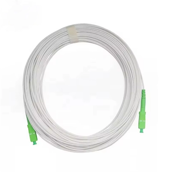
The first thing you should do is locate the fiber optic cable that comes from the service provider. Once inserted, make sure it is. However, setting up a fiber optic connection to your router can seem daunting if you're unfamiliar with the process. This comprehensive guide combines industry standards with field-tested practices to ensure you achieve a rock-solid. Setting up a fiber internet connection requires understanding key hardware components and following a specific connection sequence to establish your home network. This guide details the necessary physical and digital steps to connect your fiber line and activate your internet service. The technician powers, tests, and activates the connection to confirm full speed and signal quality. * In some instances, the ONT and the router are all in the same device, generally called a combo unit. Here's a step-by-step guide to help you through it. Understand the Basics Before diving in, familiarize yourself with the components involved:. Tecnobits - Router - How to connect a fiber optic cable to the router Hello, Tecnobits! 👋 Connecting fiber optic cables to the router so that your internet flies like a spaceship! 😉 Explore with us on our website! And don't miss our latest news. See you soon! 🚀 How to connect a fiber optic.
[PDF]
The term “hot” indicates that the bus bar is energized and constantly carrying electrical current, typically 120 volts relative to the neutral connection. This energized state makes the bus bar a direct interface between the incoming service and all the individual. The function of the bus bar is direct and clear: to convey power (as high current and/or high voltage) from the source to the load with an acceptably low voltage drop and power loss. This means using solid bars of copper (sometimes aluminum) with a cross-section size that keeps resistive losses and. A hot bus bar is a component within a residential electrical panel, often called a breaker box or load center. The bus bar is a thick metal strip that acts as the primary highway for distributing utility power throughout a home's wiring system. Code Change Summary: A new code section requires barriers at specific feeder terminations. In technical terms, a busbar is: You typically see busbars made from: Why Busbars Instead of Cables? You use busbars. New section requires barriers over uninsulated ungrounded busbars or terminals that are exposed in panelboards, switchgear, or motor control centers. Barriers shall be placed such that no energized uninsulated, ungrounded busbar or terminal is exposed to inadvertent contact by.
[PDF]
At Multilink, we offer traffic power solutions to keep traffic signals, camera equipment, illuminated street signs and other tech up and running. Power traffic signals, camera equipment, lighting and other t.
[PDF]
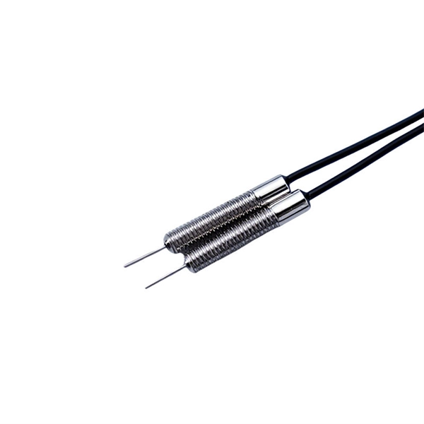
There are two main types of RF attenuators: fixed and variable. Fixed Attenuators: Provide a fixed amount of attenuation, typically designed using discrete or chip resistors. These can be further divided into:. Attenuators are designed to change the magnitude of the input signal seen at the input stage, while presenting a constant impedance on all ranges at the attenuator input. A compensated RC attenuator is required to attenuate all frequencies equally. Without this compensation, HF signal measurements. Let's look at the common types of attenuators Fixed attenuators, as their name suggests, are fixed or unchanging. These are used in applications that don't require changing levels of attenuation or where an occasional replacement of one attenuator with another is acceptable. Say we now add a 6 dB pad between. An RF Attenuator is a two-port passive electronic device designed to reduce (attenuate) the power or amplitude of an RF signal. They can adjust the signal strength by controlling the amount of attenuation, ensuring that the signal reaches the desired level for transmission in a.
[PDF]
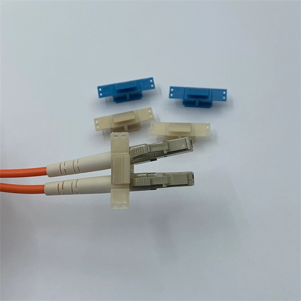
Optical isolators utilize retarders to prevent unwanted reflections, while optical attenuators adjust light intensity by varying polarization alignment. Polarization rotators and variable beam splitters allow controlled redirection of light for applications in optical. There are two primary types of attenuators—variable and fixed. Variable optical attenuators (VOAs) allow for manually adjusting the attenuation of the signal, which is ideal when there is a need to precisely balance signals strength. This is typically achieved by adjusting a screw that changes the. Beamsplitters are optical components used to split incident light at a designated ratio into two separate beams. Additionally, beamsplitters can be used in reverse to combine two different beams into a single one. Beamsplitters are often classified according to their construction: cube or plate. A beam splitter or beamsplitter is an optical device that splits a beam of light into a transmitted and a reflected beam. It is a crucial part of many optical experimental and measurement systems, such as interferometers, also finding widespread application in fibre optic telecommunications. a laser beam) into two (or sometimes more) beams, which may or may not have the same optical power (radiant flux). They are used to divide a beam of light into two or more separate beams. Depending on the design, beam splitters can either reflect a portion of the incoming light and transmit the.
[PDF]

If the LOS light on your fiber router or ONT is blinking red, it usually means Loss Of Signal. This guide explains the likely causes, the checks you can do at home, and when the issue needs technician support. The LOS light on your router indicates the status of your internet connection to the Internet Service Provider (ISP). When it's green and steady, everything is fine. However, when it blinks red or stays solid red, it signifies a Loss of Signal, a problem preventing your router from communicating. A red light on your router can be a source of frustration and confusion. Fortunately, diagnosing and resolving these issues doesn't have to be complicated. Before you panic or call tech support, there are several simple fixes you can try at home that often solve this problem in minutes. Here are some steps you can take. You might feel like you're staring into the abyss of digital darkness, wondering what went wrong. But don't despair! This guide will walk you through the most common causes of router.
[PDF]
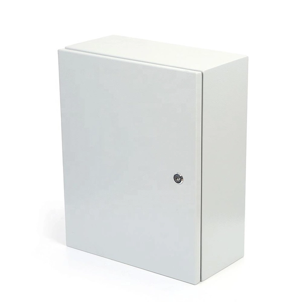
It is not recommended to place your router inside a cabinet as it can lead to poor Wi-Fi signal strength and potential overheating issues. Cabinets typically have materials that can interfere with the Wi-Fi signal, resulting in reduced coverage and slower internet speeds. For optimal performance. 💧 Water absorbs WiFi signal. Large aquariums or other significant water sources near your router can cause real connectivity issues, since water molecules are particularly effective at absorbing radio wave energy. 🏠 Router placement is your single most controllable variable. Careful planning ensures your router stays cool and your internet connection remains. Whether you're using a single Wi-Fi router or a mesh network, positioning your hardware correctly can make a major difference in speed, reliability, and coverage. Hiding your router in a cabinet or tucking it behind your TV might look tidy, but it's probably weakening your signal. After years of. In our increasingly connected world, a strong Wi-Fi signal is essential for everything from remote work to streaming entertainment. Yet many homeowners unknowingly place items near their routers that can significantly weaken their internet connection. Understanding what objects interfere with your. Positioning your router behind large furniture, under shelving units, or enclosed within cabinets can substantially degrade its performance.
[PDF]

Cable Trays* — Max two 24 in. (610 mm) wide by max 6 in. (151 mm) deep open-ladder cable tray with channel-shaped side rails formed of 0. 54 mm) thick aluminum or min 0. In practice, cable tray dimensions are a system of interrelated measurements —width, depth, length, and material thickness—that directly affect cable fill compliance, heat dissipation, structural loading, and long-term expandability. From an engineering standpoint, cable tray dimensions are not. Perforated Cable Tray System expertly constructed from high-grade stainless steel, offering exceptional durability and resistance to corrosion. With side height 100mm. A properly designed and installed cable tray system will provide. Studs — Wall framing to consist of wood studs or channel shaped steel studs. Wood studs to consist of nom 2 by 4 in. Additional studs shall be used to completely frame. Best Size: Here, deep trays (75mm to 150mm) are used since power cables are typically thick and heavy. Data cables, such as your Wi-Fi or computer ones, are extremely sensitive. They do not get hot; however, they do not like to hang or sag. In case a data cable folds in an excessive manner, the. ect the minimum bend ra-dius for cables as they exit the bottom of the cable tray. A rung spacing of 6 to 9 inches (150 to 230 mm) is preferable when the cable tray cont d for instrumentation and control applications that require additional protec eferred to support and protect numerous small.
[PDF]
