The typical specification range of return loss of a fiber connector is -15 dB to -60 dB. Return loss is also known as reflection loss. It indicates the amount of signal reflected back to the transmitting end. Return loss refers to the power loss caused by the reflection of part of the signal back to the signal source during transmission due to the discontinuity of the transmission. Insertion loss, also known as attenuation, is the loss of optical power that occurs when light passes through a fiber optic connector. It is caused by factors such as misalignment, air gaps, and imperfections in the connector components. The lower the insertion loss, the better the performance of. Reflectance (which has also been called "back reflection" or optical return loss) of a connection is the amount of light that is reflected back up the fiber toward the source by light reflections off the interface of the polished end surface of the mated connectors and air. It is also called. Insertion Loss (IL) is the amount of optical power lost as the signal travels from one point to another in a fiber optic link, usually across connectors or splices. Formula for. In optical fiber communication, insertion loss and return loss are two important parameters to evaluate the quality of interfaces between some optical fiber components, such as optical fiber connector, fiber patch cable, pigtail fiber, etc. While it's natural to have.
[PDF]

Optical return loss is the amount of light that is reflected back to the source, this reflected light is measured at each connector and splice at each point over the entire fiber link. This is always measured in dB (decibels) and will be displayed as a negative number. The closer the number is to. The polish of a singlemode fiber endface plays a significant role in reflectance. Understand what you need before you specify. The Institute of Electrical and Building the ORL story Electronics Engineers (IEEE) recently Within a fiber-optic channel or path-released new specifications within way. Optical Return Loss (ORL) in fiber optics refers to the amount of light that is reflected back toward the source in a fiber link. ORL is usually expressed in decibels (dB) as a positive value, with. Return loss (RL) is also called reflection loss. When high-speed signals enter or exit a part of an optical fiber, such as an optical fiber connector, discontinuity and impedance mismatch may cause reflection, which is the return loss of an optical fiber. Poor ORL is commonly caused by dirty connectors, poor splices, mismatched connector types, or damaged fibers. ORL is measured using ORL meters. Home Coherent Optics Optical Return Loss (ORL) Explained Comprehensive Guide to Understanding and Managing Back-Reflections in Fiber Optic Systems What is Optical Return Loss (ORL)? Optical Return Loss (ORL) is a critical parameter in fiber optic systems that quantifies the amount of light.
[PDF]

GOOD WILL INSTRUMENT (SUZHOU) CO. Browse online or download User Manual for Equipment Gw-instek GOS-652G. GW Instek GOS-652G User Manual 50MHz Cursor Readout With Delayed Sweep.. GOS-658G 20MHz Cursor Readout... GOS-652G 35MHz. Caution statements identify conditions or practices that could result in damage to this product or other property. THIS APPLIANCE MUST BE the letter E or by the earth symbol or coloured Green or Green & Yellow. EARTHED The wire which is coloured Blue must be connected to the terminal which is. y have a fraction of the total loss compared to fiber-based equivalents. FBG also provides a latency in the o der of nanoseconds as compared to microseconds in fiber-based solutions. The FBG based DCMs are designed to perfectly mimi the dispersion and dispersion slope characteristic of G. 652 fiber. g sensitivity and low water-peak level. Together they allow unlimited use of the whole telecom wavelength win ow for a great variety of applications.. GOS-653G Basic... GOS-622G. The GOS-653G/652G Series is an example of classic analog oscilloscope design. The GOS-653G /652G cover a broad range of industry applications, such as product design, assembly lines, repair & servicing, and educational purposes for EE laboratories and class experiments. Coupled with various trigger.
[PDF]

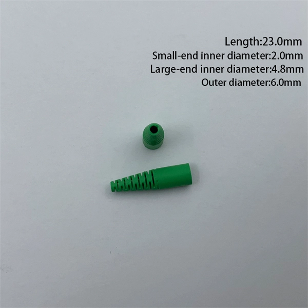
An SC/APC fiber optic adapter is a passive mechanical interface used to join two SC connectors that have angled physical contact (APC) ferrules, typically polished at 8°. Fiber couplers belong to the basic components of many fiber-optic setups. Note that the term fiber coupler is used with two different meanings: It can be an optical fiber device with one or more input fibers and one or more output fibers. It covers a wide range of fiber optic devices such as optical splitters, optical combiners, and optical couplers. A fiber optic coupler is a device that can distribute the optical signal. This small, inexpensive component is critical for aligning and mating two SC/APC connectors while preserving low insertion loss and ultra‑high return loss performance. Its core function is to distribute (split) or combine (combine) optical power while maintaining the spectral composition of the signal. The device allows the transmission of light waves through multiple paths. It functions by dividing a single incoming light path into multiple outgoing paths, or by combining light from several input paths into a single output fiber. This capability is fundamental.
[PDF]
We tested 100+ combinations of power, speed, frequency, and 12 different metals over 3 weeks of testing on 12 different metals. These are the EXACT settings that work for us every single time. No more ruined $2026. Adjusting cutting speed or gas pressure is like modifying your driving style to suit road conditions; calibration is ensuring the wheels themselves are perfectly aligned from the start. It is an exacting, methodical process designed to detect and correct any gaps between a machine's physical. Tektronix state-of-the-art calibration laboratory offers a comprehensive range of services for fiber optic test and measurement equipment. Whether you're dealing with laser sources, LED sources, optical power sensors, or optical spectrum analyzers, we've got you covered. Our accredited calibration. Loading editor. From manufacturing floors to research labs, our optical calibration services guarantee that your instruments, whether for fiber optics, photometry, or dimensional inspection, deliver precise, traceable results you can trust. All settings are calibrated. Whether you need to inspect a part or calibrate your Laser Tracker, API Metrology has the best products on the market and the most knowledgeable staff of expert metrologists. API now offers both on site and online virtual demos for you to get to know us and our products. API METROLOGY SERVICES can.
[PDF]

The max insertion loss of a fiber patch cable is 0. 75 dB (the maximum acceptable value) in the TIA standard. Insertion loss (IL) and return loss (RL) are key performance indicators of fiber optic patch cords. This article explains their concepts, standards, testing methods, and FiberMania's quality assurance workflow to ensure optimal network performance. Fiber optic patch cords are crucial components in. A: Fiber optic loss refers to the reduction in signal strength as it travels through the fiber optic cable. This can be due to various factors, including attenuation, connectors, and splices. Q: How is fiber optic loss measured? A: Fiber optic loss is typically measured using an Optical Loss Test. The estimate, called a "loss budget" is calculated using typical component losses for each part of the cable plant - the fiber, splices and/or connectors. If the measured loss exceed the calculated loss by a significant amount (remembering the inherent uncertainty in all measurements), the system. Insertion loss is usually shortened to IL, and the unit of measurement for insertion loss is dBm. ) in transmission systems. It is the power attenuation of the signal after. At TARLUZ, we specialize in manufacturing high-performance fiber optic patch cords that comply with global industry standards, ensuring optimal signal integrity and long-term stability.
[PDF]
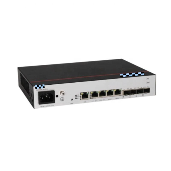
A well-chosen patch panel not only organises your fibre connections but also provides protection and flexibility for future expansions. In this comprehensive guide, we'll explore the key factors to consider when selecting the perfect patch panel for your network infrastructure. Choosing the right fiber optic patch panel is one of the most important decisions you'll make when building or upgrading a fiber network. While patch. Whether you're planning to upgrade your home internet connection or just curious about how fiber technology works, understanding the essential fiber optic equipment is the first step. From the optical network terminal to the router that brings your home online, each piece plays a critical role in. Structured wiring begins with a structured networking panel. These panels have ports for input cables and output cables. The right structured wiring can deliver top performance from your electronics. The panels accept cable from outside providers to distribute the signals to each room of your home. If you already know what your project requires, check out our complete Fiber Patch Panel selection. What is a Fiber Patch Panel? Fiber optic patch. Fiber optic installation is the way to go! It's super reliable and perfect for streaming, gaming, or using multiple devices. This guide breaks down the process in easy steps so you know what to expect. Aerial Service Drop: A cable coming from a pole to your house, connected at a small box called an.
[PDF]
Yes, single-mode fiber can transmit and receive data simultaneously. There are two ways to achieve this. We use wavelength division multiplexers (WDM Transceivers) to use this method. The single-mode optical fiber is designed and engineered to carry one single light mode in a minimal core diameter. This type of fiber is used for transmitting signals over long distances. It is specified as the best for especially long-distance applications than multimode fiber. Modes are the possible solutions of the Helmholtz equation for waves, which is obtained by combining. A single-mode fiber optic cable is an optical fiber designed to propagate light signals over long distances with minimal attenuation. It comprises one glass or plastic fiber and features a tiny core of about 8-10 microns in diameter. This small core permits only one light mode to propagate through. For a long time, fiber optic communication required two strands of fiber to accomplish full-duplex transmission—one strand for transmitting and the other for receiving. The core of the fiber is made of a highly transparent material, which allows the light to travel through it with minimal attenuation or loss of signal. This saves space and money. Dual fiber modules use two fibers.
[PDF]
The securing, storing and supporting of fiber optics and splices makes up an important step of fiber optic deployments in the field. Whether connecting to aerial or underground cables, telecommunication.
[PDF]

Different networks have different needs when it comes to fiber optic joint closures. At Multilink, we have a variety of closures to meet these needs, including inline types and drop terminals. In our selection, you can find the following termination. Different networks have different needs when it comes to fiber optic joint closures. At Multilink, we have a variety of closures to meet these needs, including inline types and drop terminals. In our selection, you can find the following termination enclosures and splice boxes for use with different cable sizes and numbers of drops: Optima™: The Op. The securing, storing and supporting of fiber optics and splices makes up an important step of fiber optic deployments in the field. Whether connecting to aerial or underground cables, telecommunications companies rely on fiber optic closures to protect and facilitate fiber splices and regular maintenance in Fiber to the Home (FFTH) and other indoo. With more than 35 years of experience, Multilink is a leader in the telecommunications industry. We make innovative products and help our customers succeed by providing high-quality equipment that's laboratory tested and proven to perform. Telecommunications companies often have unique requirements for their equipment. If you have a specific fiber.
[PDF]
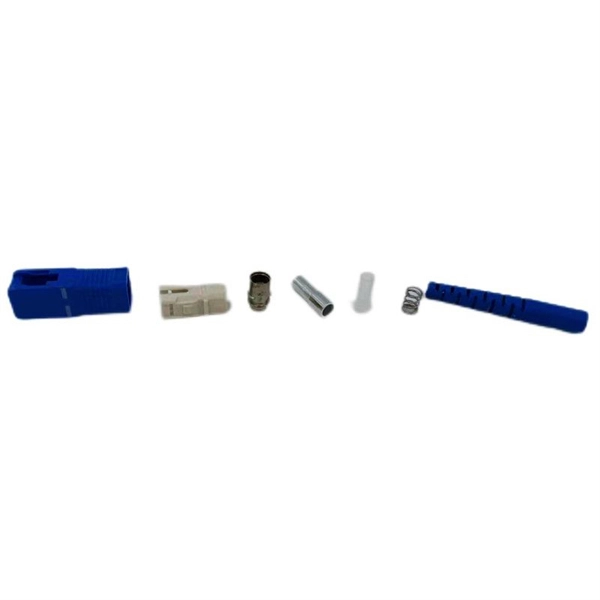
In this guide, we'll walk you through the entire process of preparing fiber optic cable for splicing and termination to fiber connectors. We'll explore the necessary tools, safety precautions, and step-by-step procedures for cable connectors, mechanical and fusion. In this guide, you will find a chronological description of the fusion splicing process, the principal technical standards, and answers to the real-life questions network engineers and procurement teams may have. Therefore, we will also touch on cost factors, risk management, and best practices in. In this guide, we cover the basics of fiber optic splicing, how to perform splicing using two different methods, and finally some best practices to perform good fiber splicing. What is Fiber Optic Splicing and Why is it Needed? – #1. Two types of splices are used in fiber optic cabling one is Mechanical the other is Fusion. Before jumping into the physical steps, it's important to understand the two primary methods of fiber splicing: fusion splicing and. Learn how to splice fiber optic cable step by step in this complete guide! In this video, you'll see the full fiber splicing process — from fiber preparation, cleaving, and fusion splicing to final testing. For network managers and technicians, a poor splice can lead to significant signal degradation, network downtime, and costly troubleshooting.
[PDF]
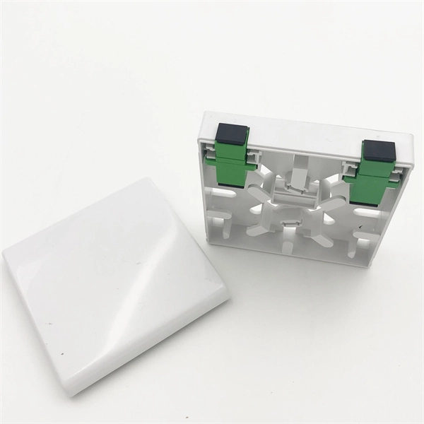
Feature -- 2 ports optical fiber distribution box is used for the fusion splicing, splitting, wiring transmission and other functions of the optical transmission terminal. It can effectively terminate, protect and manage the optical cable. It is a necessary equipment in network. Fibertech Misr supplies all components of fiber optic networks of fiber optic cable, patch cord, Pigtail, Adaptor, closure, Connector, media converter, over 11 years, the implementation of Telecommunications projects, Training for Welding, Measuring,FTTH,GPON, SDH,DWDM,CCTV,IP TV. Explore high-capacity Fiber Optic Patch Panels, Termination Boxes, and ODF solutions for robust telecommunications infrastructure. Our expertise, high-quality products, optimal cost/performance ratio, and time-saving approach set us apart from the competition. All Rights reserved. © 2026 COMTEC-SOL. COMtec Integrated Solutions, we are a leading manufacturer and vendor of cutting-edge Telecom infrastructure solutions, specializing in both Copper and Optical Fiber technologies. It's perfect for use in data centers and other telecommunications applications, and it's sure to provide you with the excellent performance that you need. Streamline your fiber connectivity with our premium Fiber Optic Patch Panels and ODF systems. Designed for reliability and ease of use, our rack-mount and wall-mount solutions provide the perfect environment for splicing, terminating, and managing your critical fiber optic connections.
[PDF]

Fiber Optic Welding How To Joint Fiber Optic Cablesplicing fiber optic cable,fiber optic splice,fiber optic,fiber optics,fiber splice,how to splice,fibre opt. The optical fiber connection adopts the fusion splicing method. The whole process is similar to the welding of metal wires, and it is generally carried out by electric isolation. At the moment, there are two methods of connection: Thermal welding of optical fibers consists in bringing the ends of the conductor to melting using a fiber optic splicer, and more specifically - located inside the electrodes. The welded ends are then pressed and a weld is formed. The most work is waiting for installers, whose tasks can be divided into several stages: In this part, we will deal with the second stage, i. welding, which is considered to be one of the most difficult parts of installers' work in. Open the stripping tube and wipe the grease on the optical fiber with toilet paper and alcohol cotton. On the welding disc, make the optical fiber precoil first and cut the optical fiber into an appropriate length to facilitate the coil fiber work after welding. Add heat shrink tube. Procedure. Another method is to use the so-called mechanical welding. It uses special parts that are prepared in advance to connect the two ends. Thanks to this, you can connect two ends of the cable with a ready-made splice, without the need to use an optical fiber splicer. While this method may appear to be.
[PDF]
Pigtail, also known as pigtail, has only one end with a connector, and the other end is a broken end of a fiber optic cable core. It often appears in fiber optic terminal boxes. (couplers, jumpers, etc. are also used between. Long tail fibers consist of a phage-proximal and a phage-distal rod, each around 80 nm long and attached to each other at a slight angle. The phage-proximal rod is formed by a homo-trimer of gene product 34 (gp34) and is attached to the phage-distal rod by a monomer of gp35. are also used between them). One. The tailed phage T4 encodes a specialized device for this purpose, the long tail fiber (LTF), which allows the virus to move on the bacterial surface and find a suitable site for infection. Consequently, the infection efficiency of phage T4 is one of the highest, reaching the theoretical value of. Bacteriophages, often called phages, are viruses that infect and replicate within bacteria. These tiny biological entities play a significant role in microbial ecosystems. Tail fibers are structures on the phage that mediate their initial interaction with bacterial hosts, allowing them to recognize. The tail (Fig. Infection is initiated with the reversible attachment of six long tail fibers (LTFs) to the cell's outer layer of lipopolysaccharides, followed by transformation of the.
[PDF]

This practical file details experiments conducted in Optical Fiber Communication, covering modulation techniques, system components, and performance analysis. An optical fiber is a glass or plastic fiber designed to guide light along its length, widely used in fiber-optic communication, which permits transmission over longer distances and at higher data rates than other forms of communications. Fiber-optic communication is a method of transmitting. Availability of plastic optical fiber (POF) The plastic optical fiber used in some of these experiments is available for science distributors. It is a 1000micron (1mm) POF available from several suppliers. FOA has samples available at no cost for teachers at schools in the US. Key experiments include amplitude modulation, frequency modulation, and pulse width modulation, aimed at understanding fiber optic systems. This document summarizes 10 experiments on optical fiber communication: 1. Studying a 650mm fiber optic analog link and the relationship between input and received signals. Optical fiber communication Laboratory Optical fiber communication Laboratory List of Experiments: 1. To set up a analog optical fiber link 2. To measure the characteristics of LED and LASER 5. Tech curriculum designed to provide a comprehensive understanding of optical fiber communication systems. This lab offers an immersive, web-based simulator that enables you to explore and experiment with key concepts in optical.
[PDF]