Distributed Fiber Optic Sensing (DFOS) systems, using coherent light pulses, detect physical characteristics such as temperature and strain. DFOS enable localized measurements over long distances, leveraging Rayleigh, Brillouin, and Raman scattering. This review summarizes recent progress and emerging trends in multiparameter optical fiber sensing, emphasizing techniques that enable the simultaneous measurement of temperature, strain, acoustic waves, pressure, and other environmental quantities within a single sensing network. This technology is revolutionizing industries from infrastructure monitoring. Distributed Fiber Optic Sensing (DFOS) systems provide critical asset monitoring by utilizing standard fiber optic cables as sensors. These systems enable precise measurement of temperature, strain, and acoustic signals along the entire length of an optical fiber. Such capabilities.
[PDF]
Different methods have been developed to measure cable forces, including the traditional direct strain measurement method, the oil pressure meter method, the low-cost vibration frequency method, the high-accuracy magnetic flux sensor method in the lab., and acoustic. This study aimed to develop a spiral deployment scheme of distributed fiber optic sensors (DFOS) and to monitor/assess the post-tensioned force in seven-wire twisted steel cables, based on the pulse-pre-pump Brillouin optical time domain analysis. Each DFOS was placed in a spiral shape between two. Distributed Optical Fiber Sensing (DFOS) transforms standard fiber optic cables into powerful sensors capable of detecting temperature, strain, and acoustic signals at thousands of measurement points over long distances. Such capabilities. l method of measuring force by means of bending a Fiber Fabry-Perot-{FFP-) resonator is described. This interferometric FFP-sensor is easily applicable to AC orce measurements, but makes temperature compensati on schemes necessary if DC ntity that can various measuring parame, accelerat of di. Distributed sensors hold a unique position in the realm of sensing technologies. Unlike point sensors, they can measure and provide a continuous spatial distribution of a physical quantity, effectively creating a mapped profile of the parameter of interest. A well-known example is RADAR, and more.
[PDF]
Distributed fibre optic sensing, including DTS and DTSS technologies, has a wide range of applications across various industries. Here are some key areas where these innovative technologies are making.
[PDF]
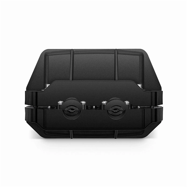
Rayleigh scattering -based distributed acoustic sensing (DAS) systems use fiber optic cables to provide distributed strain sensing. In DAS, the optical fiber cable becomes the sensing element and measurements are made, and in part processed, using an attached optoelectronic device. These systems enable precise measurement of temperature, strain, and acoustic signals along the entire length of an optical fiber. DFOS technology plays a crucial. ONYXTM the flagship platform from Sintela now delivers a customizable all-in-one, simple and cost-effective solution for your distributed fiber-optic sensing needs. Representing the next step in the evolution of Distributed Fiber Sensing, ONYX™ converts existing telecommunications fiber-optic cable. Distributed acoustic sensing systems (DAS) are fiber optic based optoelectronic instruments which measure acoustic interactions along the length of a fiber optic sensing cable. The unique feature of a distributed acoustic sensing system is that it provides a continuous (or distributed) temperature. Distributed Acoustic Sensing (DAS) is a cutting-edge technology that uses optical fiber to sense and identify multiple parameters over extended distances remotely. The technology leverages the Rayleigh backscatter theory to detect vibrations and sounds along the fiber Fiber optic-based Distributed.
[PDF]
Fiber optic pressure sensors use light modulation to measure pressure, offering high sensitivity, EMI immunity, and wide-ranging applications. Fiber-optic sensing (FOS) technology has emerged as a cutting-edge research focus in the sensor field due to its miniaturized structure, high sensitivity, and remarkable electromagnetic interference immunity. These sensors are gaining popularity. Fiber optic pressure sensors are generally categorized into two main types: non-interferometric and interferometric. Figure 1 depicts a simplified structure of a non-interferometric fiber optic pressure sensor. Fiber Optic Pressure Sensors work on the.
[PDF]
High-definition temperature sensing based on the natural Rayleigh backscatter in optical fiber delivers a virtually continuous line of temperature measurements with sub-millimeter spatial resolution. 1. Map temperat.
[PDF]

Distributed Fiber Optics Sensing (DFOS) is a mature technology, with known, tested, verified, and even certified performance of various interrogators and measurement methods, which include Distributed Temperature Sensing (DTS), Distributed Temperature-Strain Sensing. Distributed Fiber Optics Sensing (DFOS) is a mature technology, with known, tested, verified, and even certified performance of various interrogators and measurement methods, which include Distributed Temperature Sensing (DTS), Distributed Temperature-Strain Sensing. Distributed Fiber Optics Sensing (DFOS) is a mature technology, with known, tested, verified, and even certified performance of various interrogators and measurement methods, which include Distributed Temperature Sensing (DTS), Distributed Temperature-Strain Sensing (DTSS), and Distributed Acoustic. FEBUS Optics is the world reference in DFOS, distributed fiber optic sensing systems (DAS, DTS and DSS), to reduce the environmental impact of human activity, protect people, and optimize production. FEBUS provides state-of-the-art devices and turnkey solutions based on its patented technologies.
[PDF]
is a and the second largest in. Located in the, it is bordered by in the north and in the south. Bhutan is separated from by the Indian state of and from by the Indian states of and. With over 700,000 inhabitants, its population is the seventh largest in. is its capital and largest city, while.
[PDF]
Modern fiber-optic communication systems generally include optical transmitters that convert electrical signals into optical signals, to carry the signal, optical amplifiers, and optical receivers to convert the signal back into an electrical signal. The information transmitted is typically generated by computers or.
[PDF]
In this paper, we propose and experimentally demonstrate a Michelson interferometer (MI)-based inclinometer using a simple configuration: a misalignment-spliced single mode fiber (SMF) with end coating. A fiberoptic sensor that uses diverse fiber units to support various applications in virtually any environment. These are reliable and easy-to-use devices that have high power, can automatically adjust to real-time conditions, and have a straightforward display that eliminates any guesswork. This. An in-fiber Michelson interferometer (MI)-based inclinometer, which consists of misalignment-spliced fiber with end coating, is proposed and experimentally demonstrated. The incident light divided at the misalignment-spliced joint is reflected at the end coating, and then re-coupled into the fiber. Jose Miguel Lopez-Higuera: Handbook of Optical Fiber Sensing Technology, John Wiley & Sons, 2002. P 603 Radiation absorption excites an orbital electron to a higher energy level.
[PDF]

Optical fibers or fiber cables can be used for transmitting optical power from a source to some application. In their served areas will be power generating stations, alternative energy sources (solar, wind, geotherman, etc. ), substations for distribution and microgrids. These networks must be monitored and managed to ensure reliable power for the utility's customers. For monitoring and managing networks. Low voltage cables are mounted on poles in the "telecom space," well below power cables. Optical power ground wire (OPGW) is an electrical power ground with fiber optics in the center of the conductor. That conversion can be done with a photovoltaic cell. The Commission, on June 22, 1965, noting that the increasing demand for underground electric and communication facilities in California has brought about substantial increases in the construction of such facilities, and that it appeared it may be desirable, pursuant to Sections 761, 768 and 8056 of. One choice is optical power ground wire (OPGW). This conductive cable is run at the top of the tower or pole to be the ground conductor and protect the power cables from lightning. The fiber. While fiber optics is essential for internet service providers to deliver higher bandwidth and faster transmit speeds, there are also many crucial benefits of fiber optics in energy and power. Utility companies face various challenges as they work to deliver reliable energy to homes and industries.
[PDF]

A Fiber Optic Gyro, or FOG, is defined as an inertial sensor capable of measuring angular rate with high accuracy and long-term stability. No rotating masses, as in mechanical gyros, are required; the revolution is detected by light traveling inan optical fiber. Inertial sensor is a type of sensor that can measure the motion state of an object. They help achieve precise perception of object position, velocity, and direction by detecting data such as acceleration, rotation, and tilt. Inertial sensors have a wide range of applications, from autonomous. A fiber-optic sensor is a sensor that uses optical fiber either as the sensing element ("intrinsic sensors"), or as a means of relaying signals from a remote sensor to the electronics that process the signals ("extrinsic sensors"). Fibers have many uses in remote sensing. However, since the early 1930s, numerous scientists, engineers, and. In particular, small navigation sensor size allows the introduction of guidance, navigation, and control into applications previously considered out of reach (e., artillery shells, personal navigation). Three major technologies have enabled advances in military and commercial capabilities: Ring. Delivering resilient, high-precision navigation solutions that operate across land, air, and sea. ANELLO Photonics builds next-generation inertial sensors you can trust. Therefore, this optically based.
[PDF]
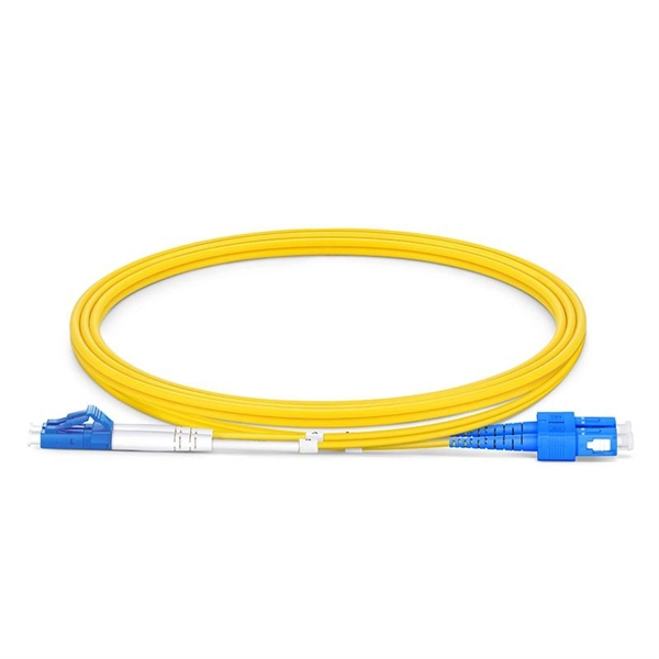
Single mode and multimode fiber optic cables are two different types of fiber optic cable aimed at different use cases. Single mode cables are typically made with a single strand of glass at their core, leading to a n.
[PDF]

The procedures in this document describe basic inspection techniques and processes of cleaning for fiber optic cables, bulkheads, and adapters used in fiber optic connections. Note: This document is intended for use by service personnel, field service technicians, and. There are three main principles that needs to be taken in consideration for an efficient optical connection: a perfect core alignment, perfect physical contact and dirt-free connectors. It is important that every fiber connector be inspected and cleaned prior to mating. That advice is misguided. It could hurt an installer or get them sued by an irate network owner. This guide outlines best practices for maintaining and inspecting installed fiber optic infrastructure, enabling network owners to keep their systems running at peak efficiency. Fiber optics infrastructure consists of optical fiber cables, connectors, splice enclosures, distribution panels, and. Small oil micro-deposits and dust particles on fiber optic cable optical surfaces may cause a loss of light or degraded signal power which may ultimately cause intermittent problems in the optical connection. Fiber optic testing and maintenance protocols not only maintain the reliability of the network, but also allow for early detection of potential failures and optimization of performance.
[PDF]

The typical specification range of return loss of a fiber connector is -15 dB to -60 dB. Return loss is also known as reflection loss. It indicates the amount of signal reflected back to the transmitting end. Return loss refers to the power loss caused by the reflection of part of the signal back to the signal source during transmission due to the discontinuity of the transmission. Insertion loss, also known as attenuation, is the loss of optical power that occurs when light passes through a fiber optic connector. It is caused by factors such as misalignment, air gaps, and imperfections in the connector components. The lower the insertion loss, the better the performance of. Reflectance (which has also been called "back reflection" or optical return loss) of a connection is the amount of light that is reflected back up the fiber toward the source by light reflections off the interface of the polished end surface of the mated connectors and air. It is also called. Insertion Loss (IL) is the amount of optical power lost as the signal travels from one point to another in a fiber optic link, usually across connectors or splices. Formula for. In optical fiber communication, insertion loss and return loss are two important parameters to evaluate the quality of interfaces between some optical fiber components, such as optical fiber connector, fiber patch cable, pigtail fiber, etc. While it's natural to have.
[PDF]