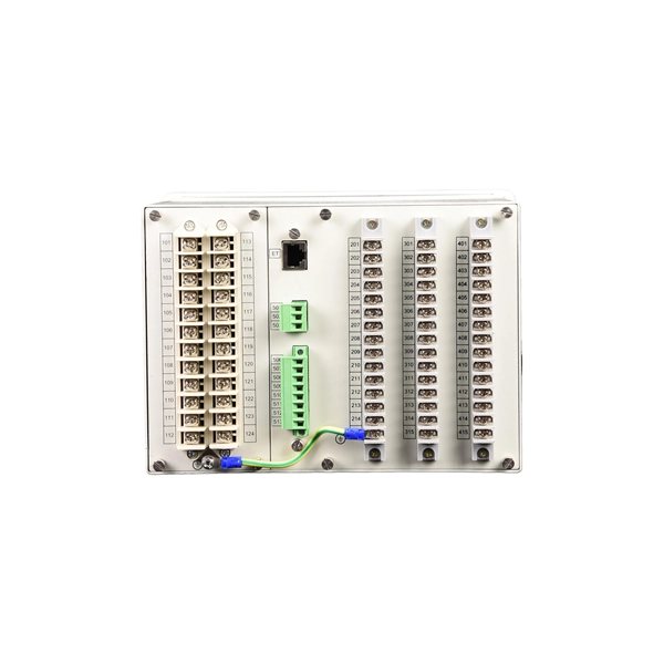
In an Ethernet patch panel diagram, each port on the patch panel is represented by a numbered or labeled square or circle. The diagram typically includes details such as the port numbers, cable types, and the devices connected to each port. Ethernet patch panel diagram is a visual representation of the connections between Ethernet cables and network devices, such as switches and routers. It provides a clear overview of how the network is structured, allowing network administrators to easily troubleshoot and manage the network. This information can be used to track the location of devices, their serial numbers, and their IP addresses. Change Management: Patch panel connection diagrams can be used to track. A patch panel is an essential component in a network system that provides a central location for connecting multiple devices or cables. The patch panel serves as. A pair of managed Gigabit Ethernet rack-mount switches, connected to the Ethernet ports on a few Panduit patch panels using Category 6 patch cables. (All equipment is installed in a standard 19-inch rack. Each port has a patch connection that links it to another port in another part of your building.
[PDF]
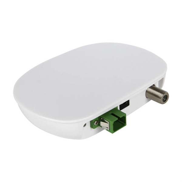
A cable drop refers to the final segment of a communication link that connects the primary network or distribution point to a specific user's premises, such as a home, office building, or data center. This connection is typically the last leg of the network, hence the term "last-mile. A drop cable, commonly referred to as a cable drop, is a critical component in network connectivity, typically used to connect a computer's Network Interface Card (NIC) to a wall plate. Serving as the final link in the networking chain, it plays a vital role in ensuring a stable and reliable. A cable drop is a single run of cable from a distribution point to its endpoint, whether that's a coaxial line from a utility pole to your house, an Ethernet cable from a server room to a desk, or a power line from an overhead system to a workstation. This cable runs from a point on the utility network (such as a pole, pedestal, or vault) directly to the side of a home or business. It delivers. At the core of this connectivity is drop cable, a type of cable essential for delivering high-speed internet, phone, and TV services directly to homes and businesses. " Cable. Let's start with the drop cable meaning. Think of it as the “last mile” of the fiber network — the part that brings the signal directly to you.
[PDF]

A beamsplitter is a common optical component that partially transmits and partially reflects an incident light beam, usually in unequal proportions. In addition to the task of dividing light, beamsplitters can be employed to recombine two separate light beams or images into a single. Beamsplitters are fundamental components in optical engineering, serving to precisely divide a single input beam of light into two distinct output beams. This division allows for the simultaneous analysis or utilization of the light's properties along two separate paths. It is a crucial part of many optical experimental and measurement systems, such as interferometers, also finding widespread application in fibre optic telecommunications. a laser beam) into two (or sometimes more) beams, which may or may not have the same optical power (radiant flux). Different types of beam splitters exist, as described in the. The beam splitter splits and then recombines infrared radiation, while the detector picks up the resulting signal. It's sensitive to both intensity and frequency. Together, they decide just how accurately an instrument captures those unique infrared “fingerprints” from different substances.
[PDF]

PDH called Parallel Data Highway, is a quasi-synchronous transmission technology based on digital transmission. PDH defines multiple multiplexing levels, such as 2Mbps (E1), 8Mbps (E1). This page defines various terms related to the optical domain. It covers SDH, PDH, SONET, DWDM, FTTH, WDM, PDMA, wavelength converters, optical ADMs, EDFAs, and SOAs. Converts optical light from one wavelength to another. Definitions of common terms related to fibre optics, including SDH, PDH. Part I. SDH is a synchronous TDM technology that multiplexes low-order signals into high-order signals. Because the entire network is. PDH (Plesiochronous Digital Hierarchy), is an early digital transmission standard to handle the transport of digital signals over copper and fiber-optic networks. It appeared in the 1980s and developed rapidly. PDH, in the form of traditional point-to-point connection of various media. The term "plesiochronous" refers to the fact that PDH operates with nearly synchronized timing between. The method was developed to replace the plesiochronous digital hierarchy (PDH) system for transporting large amounts of telephone calls and data traffic over the same fiber without the problems of synchronization. SONET and SDH, which are essentially the same, were originally designed to transport.
[PDF]

It consists of 5 buttons. A power button, a button to turn on the VFL, a lambda button to set the wavelendth, a REF button, and a dBm/W button to set the unit of power. First, you check the initial power of a light signal. Then you check its power at the other end of optical. OPM interface: insert the fiber to be tested, test the optical power. REF/dB key: Short press the dB to switch unit, click once nW/dBm/dB to enter the upper clear data, press and hold until REF is displayed on the screen, and set the current optical power as reference value, enter the relative. There are two buttons on this meter. One is the power button, used to turn the meter on/off. At the top, there is a sensor that detects the light beam. The. at -22 (or 25 with tone on)). To do this you. Active Equipment Power Measurement Fiber Continuity Patch Cable Testing Check MM Reference Cables - Dual OWL MM Sources Check MM Reference Cables - WaveSource MM Sources Check SM Reference Cables - Laser OWL SM Sources Check SM Reference Cables - WaveSource SM Sources. Power-off: Press and hold “MODE” key for 2 seconds or more until “OFF” displays on the screen. Note: This instrument will shut down automatically without receiving any operation instruction for 10 minutes. Function selections: It.
[PDF]
LC pigtails are short fiber optic cables which have one connector on their one end and a bare fiber on the other. The connector type most commonly used is the LC connector, known for its compact size and ease of use. It is usually suitable for field termination using a mechanical or fusion splicer. Compared with quick termination or epoxy and polish connections placed on the field. The optical fiber connector is a kind of detachable passive optical component used in the connection between fiber to fiber, the light source to the fiber, and fiber to the detector to achieve the light maximize coupling to the receiving fiber. According to the estimating, there are hundreds of. HOLIGHT fiber pigtails ensure low-loss termination. Available in SC, LC, FC, ST, singlemode & multimode for precise splicing. LC pigtails come in simplex (single fiber) or duplex (two fibers) configurations. Executive Summary: A fiber optic pigtail is one of the most commonly specified yet least understood components in structured cabling. Get the wrong connector type, the wrong polish, or skip proper fusion splicing technique—and you're looking at elevated signal loss, increased back reflection, and a. Fiber optic pigtail has an optical connector pre-installed on one end and a length of exposed fiber at the other end. LC series pigtail normally comes with 0. 9mm cable diameter, UPC/PC and APC versions, SM, MM, OM3 and OM4 modes. 5 meter, also can be as customer's.
[PDF]