In a theatre, a specialty panel known as a dimmer rack is used to feed stage lighting instruments. A U.S. style dimmer rack has a 208Y/120 volt 3-phase feed. Instead of just circuit breakers, the rack has a solid state electronic dimmer with its own circuit breaker for each stage circuit. This is known as a dimmer-per-circuit arrangement. The dimmers are equally divided across the three incomin. OverviewA distribution board (also known as panelboard, circuit breaker panel, breaker panel, electric panel, fuse box or DB box) is a component of an that divides an electrical power feed into subsidiary. North American distribution boards are generally housed in enclosures, with the positioned in two columns operable from the front. Some panelboards are provided with a door covering th. This picture shows the interior of a typical distribution panel in the United Kingdom. The three incoming phase wires connect to the busbars via a main switch in the centre of the panel. On each side of the panel are two.
[PDF]
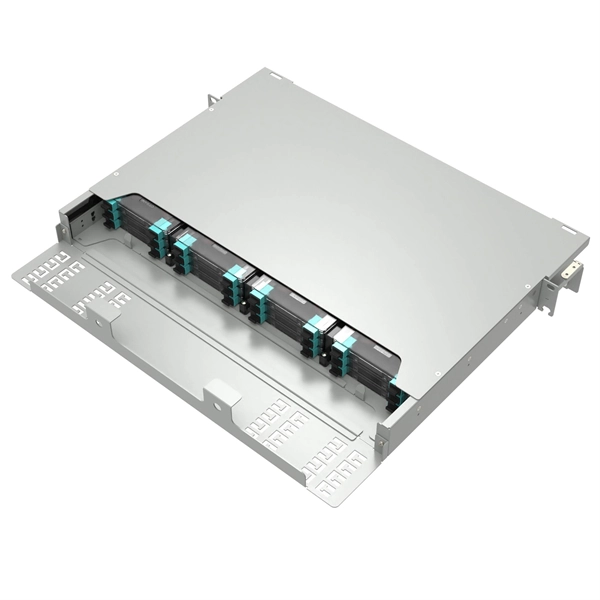
LC pigtails are short fiber optic cables which have one connector on their one end and a bare fiber on the other. The connector type most commonly used is the LC connector, known for its compact size and ease of use. It is usually suitable for field termination using a mechanical or fusion splicer. Compared with quick termination or epoxy and polish connections placed on the field. The optical fiber connector is a kind of detachable passive optical component used in the connection between fiber to fiber, the light source to the fiber, and fiber to the detector to achieve the light maximize coupling to the receiving fiber. According to the estimating, there are hundreds of. HOLIGHT fiber pigtails ensure low-loss termination. Available in SC, LC, FC, ST, singlemode & multimode for precise splicing. LC pigtails come in simplex (single fiber) or duplex (two fibers) configurations. Executive Summary: A fiber optic pigtail is one of the most commonly specified yet least understood components in structured cabling. Get the wrong connector type, the wrong polish, or skip proper fusion splicing technique—and you're looking at elevated signal loss, increased back reflection, and a. Fiber optic pigtail has an optical connector pre-installed on one end and a length of exposed fiber at the other end. LC series pigtail normally comes with 0. 9mm cable diameter, UPC/PC and APC versions, SM, MM, OM3 and OM4 modes. 5 meter, also can be as customer's.
[PDF]

It consists of 5 buttons. A power button, a button to turn on the VFL, a lambda button to set the wavelendth, a REF button, and a dBm/W button to set the unit of power. First, you check the initial power of a light signal. Then you check its power at the other end of optical. OPM interface: insert the fiber to be tested, test the optical power. REF/dB key: Short press the dB to switch unit, click once nW/dBm/dB to enter the upper clear data, press and hold until REF is displayed on the screen, and set the current optical power as reference value, enter the relative. There are two buttons on this meter. One is the power button, used to turn the meter on/off. At the top, there is a sensor that detects the light beam. The. at -22 (or 25 with tone on)). To do this you. Active Equipment Power Measurement Fiber Continuity Patch Cable Testing Check MM Reference Cables - Dual OWL MM Sources Check MM Reference Cables - WaveSource MM Sources Check SM Reference Cables - Laser OWL SM Sources Check SM Reference Cables - WaveSource SM Sources. Power-off: Press and hold “MODE” key for 2 seconds or more until “OFF” displays on the screen. Note: This instrument will shut down automatically without receiving any operation instruction for 10 minutes. Function selections: It.
[PDF]

PDH called Parallel Data Highway, is a quasi-synchronous transmission technology based on digital transmission. PDH defines multiple multiplexing levels, such as 2Mbps (E1), 8Mbps (E1). This page defines various terms related to the optical domain. It covers SDH, PDH, SONET, DWDM, FTTH, WDM, PDMA, wavelength converters, optical ADMs, EDFAs, and SOAs. Converts optical light from one wavelength to another. Definitions of common terms related to fibre optics, including SDH, PDH. Part I. SDH is a synchronous TDM technology that multiplexes low-order signals into high-order signals. Because the entire network is. PDH (Plesiochronous Digital Hierarchy), is an early digital transmission standard to handle the transport of digital signals over copper and fiber-optic networks. It appeared in the 1980s and developed rapidly. PDH, in the form of traditional point-to-point connection of various media. The term "plesiochronous" refers to the fact that PDH operates with nearly synchronized timing between. The method was developed to replace the plesiochronous digital hierarchy (PDH) system for transporting large amounts of telephone calls and data traffic over the same fiber without the problems of synchronization. SONET and SDH, which are essentially the same, were originally designed to transport.
[PDF]

A beamsplitter is a common optical component that partially transmits and partially reflects an incident light beam, usually in unequal proportions. In addition to the task of dividing light, beamsplitters can be employed to recombine two separate light beams or images into a single. Beamsplitters are fundamental components in optical engineering, serving to precisely divide a single input beam of light into two distinct output beams. This division allows for the simultaneous analysis or utilization of the light's properties along two separate paths. It is a crucial part of many optical experimental and measurement systems, such as interferometers, also finding widespread application in fibre optic telecommunications. a laser beam) into two (or sometimes more) beams, which may or may not have the same optical power (radiant flux). Different types of beam splitters exist, as described in the. The beam splitter splits and then recombines infrared radiation, while the detector picks up the resulting signal. It's sensitive to both intensity and frequency. Together, they decide just how accurately an instrument captures those unique infrared “fingerprints” from different substances.
[PDF]
An electrical pigtail is a short piece of wire used to connect an electrical device, such as a switch or receptacle, to the main circuit conductors within a junction box. It acts as a jumper between the device terminal and the spliced bundle of circuit wires. This technique ensures the device is. Are a pigtail and a jumper wire the same thing, how are they different ? A jumper connects two devices or terminals together. Like you can jumper the top and bottom halves of a duplex receptacle if the bridge gets broken off. You can. The most intuitive difference between the two is that only one end of the pigtail has a connector, and both ends of the jumper have a connector. Optical Fiber Jumper: also known as optical fiber connector, both ends have connectors. Similar to coaxial cable, but without mesh shielding, for jumper. This detailed guide will take you through the basics of jumper wires, their types, applications, and the step-by-step process of connecting them securely and effectively. What Are Jumper Wires? Jumper wires are insulated wires used to connect two points in a circuit. They usually come with. Pigtails play a crucial role in ensuring safe and efficient connections within electrical systems, especially when dealing with multiple wires or limited space. Understanding what a pigtail is and how it works can make your wiring projects smoother and safer.
[PDF]

Fusion splicing is the most widely used method of splicing as it provides for the lowest loss and least reflectance, as well as providing the strongest and most reliable joint between two fibers. Virtually all singlemode splices are fusion. There are two main methods of splicing: mechanical splicing and fusion splicing. This blog will delve into the nuances of each method, comparing their costs, labor efficiency, network performance, and more, to help you decide which splicing technique is best suited for your needs. Why splice? Fiber. Fusion splicing is the process of fusing or welding two fibers together usually by an electric arc. Fiber splicing means joining two optical fibers (permanently or temporarily) such that light guided in one fiber and reaching the joint (splice) can be transferred into the second fiber with low insertion loss. Another method of connecting optical fibers is termination or connectorization, which consists of processing the end of a fiber optic bundle so that it can be connected to other fibers or devices through fiber optic. Fiber Optic Cable is a form of modern network cable that has a far greater capacity than electrical communication connections. Splicing is typically required during cable installation, maintenance, or network expansion. The goal is to achieve the lowest possible optical loss (signal.
[PDF]

NPO (Near-Packaged Optics) is a transitional technology bridging traditional pluggable modules and CPO. It integrates the optical engine and GPU chip side-by-side on the same high-performance PCB or organic substrate, connected via ultra-short high-speed circuits. Its core concept is to remove digital processing units such as DSPs and CDRs from the module, constructing a purely analog "linear direct-drive" optical link. In the LPO architecture: The transmitter uses a high-linearity driver chip to directly drive the optical modulator, converting the. Near-packaged optics (NPO) helps send data faster. It puts the optical engine close to the switching chip. This makes things work better. NPO lets you upgrade easily. You do not have to redesign your whole system. It lowers energy costs. Among the emerging technologies, LPO (Linear Pluggable Optics), NPO (Near-Packaged Optics), and CPO (Co-Packaged Optics) represent three important stages in the evolution of next-generation data center optical networking. Understanding how these architectures differ is essential for designing. Traditional optical modules typically rely on DSPs (Digital Signal Processors) to handle signal equalization, retiming, and compensation, mitigating attenuation and distortion during transmission. They are not concepts at the same level, but rather.
[PDF]