Receiver sensitivity is the lowest optical power level at which an optical receiver can successfully decode data with acceptable bit error rates (BER). It's a core parameter in optical transceiver specifications, indicating the module's capability to detect weak incoming signals. The standards body governing the application sets this specified BER. For example, SONET specifies that the BER must be 10 -10 or better. What Is BER? The bit error rate (BER) measures the data transmission precision within. Receiver sensitivity stands as a critical parameter impacting an optical transceiver's functionality. It denotes a module's capability to function in challenging environments and aids network operators in determining the system's maximum reach or link margin. Lower receiver. Among a group of optical receivers, a receiver is said to be more sensitive if it achieves the same performance with less optical power incident on it. The performance criterion for digital receivers is governed by the bit-error rate (BER), defined as the probability of incorrect identification of.
[PDF]

In simple terms, Receiver Sensitivity is the minimum received optical power required at the input of a receiver for the system to achieve a specified performance level, typically defined by a maximum Bit Error Rate (BER). Think of it like listening to a distant radio station. The standards body governing the application sets this specified BER. For example, SONET specifies that the BER must be 10 -10 or better. Optical modules form the backbone of modern data center networks, enabling ultra-high-speed data transmission between servers, switches, and storage devices. In optical link design, the receiver performance parameters are like vital signs of the link, directly determining the reliability and. Receiver sensitivity shows the weakest signal your device can find. Good sensitivity gives stronger connections, even with weak signals. Always look at the dBm value in product details. A lower dBm means better receiver sensitivity. This helps you pick the best device. It denotes a module's capability to function in challenging environments and aids network operators in determining the system's maximum reach or link margin.
[PDF]

Find all you need for professionally buying optical fiber communication systems and devices: a comprehensive expert-curated directory of suppliers, scientific and technical background information, and an interactive AI-based tool with guidance for a structured decision process. T he MACOM PRISM-50D™MATP-05026D device is a 50G PAM4/NRZ PHY with integrated DSP and multiplexing functionality designed to enable single-wavelength 50G optical transceiver solutions. MACOM PRISM-50D™ is a highly integrated device offering low latency, low power, and a small foot print package. FIBERSTAMP 100G QSFP28 CLR4 optical transceiver are used for medium and long distance interconnection in data centers, complying with 100G CLR4 MSA specification and compatible with both 100G Ethernet and InfiniBand EDR transmission protocols. The product has a built-in pair of 4-channel CWDM MUX. GIGALIGHT 100G QSFP28 LR4 optical modules are used for long-distance transmission in the datacom or telecom field and are compliant with IEEE 802. 3ba 100GBASE-LR4 Ethernet transmission protocol, with optional dual-rate versions compatible with 100G Ethernet and OTN OTU4. The package contains a high-speed DFB laser chip, thermoelectric cooler, thermistor, optical isolator, and a rear-facet monitor. Contact Optilab for more information and pricing options. The Optilab DML-1550-PM-M is a directly modulated laser (DML) module with Polarization Maintaining fiber output at 1550 nm. You appear to be.
[PDF]

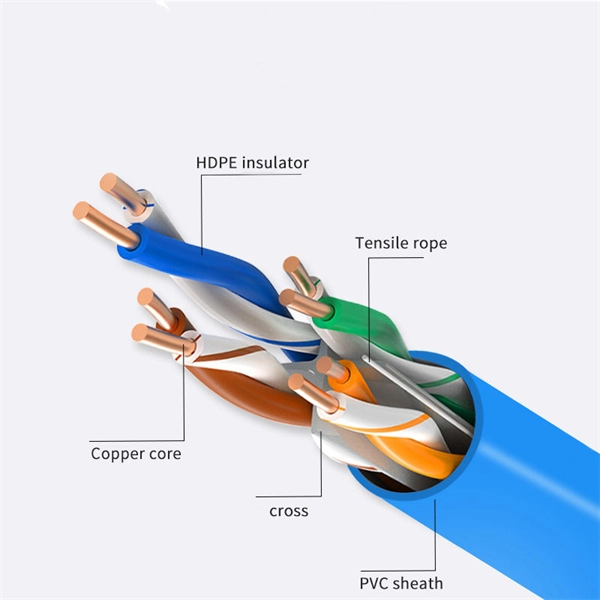
Multimode Fiber Optic Receivers are devices designed to interpret information contained in optical signals transmitted through multimode fibers. These receivers convert the optical signals into electrical signals, allowing the data to be processed and utilized by electronic systems. Multimode Fiber. They convert electrical signals into optical signals for transmission over fiber-optic cables and reverse the process at the receiving end. Now, the term 'multimode' stems from the fact that these transceivers use multimode fiber (MMF) cables, which can carry multiple beams of light — or 'modes' —. Multi-mode optical fiber is a type of optical fiber mostly used for communication over short distances, such as within a building or on a campus. Multi-mode links can be used for data rates up to 800 Gbit/s. Most systems operate by transmitting in one direction on one fiber and in the reverse direction on another fiber for full duplex operation. For applications where long-haul transmission is unnecessary, multimode SFP modules offer a practical. They have a wider core (around 50 to 62. 5 micrometers), which enables multiple modes or light paths to coexist within the fiber, thus resulting in modal dispersion at shorter distances but reducing its efficacy over longer stretches. The choice between Single-Mode Fiber (SMF) and Multimode Fiber.
[PDF]

ROSA refers to Receiver Optical Sub-Assembly, the primary function of which is to convert the optical signal transmitted from TOSA into electrical signal. ROSA contains a photodiode (PD), optical interface, metal and/or plastic housing, and electrical interface. This article will focus on the internals of the optical transceiver including the TOSA, ROSA and BOSA, and PCBA. Optical modules are devices used to connect network devices, transmit. As a key element in optical communication systems, optical transceivers serve as media between network devices to transmit and receive data. There has been lots of articles and guides on transceiver modules in the perspective of the package type while only a few of them cover the internal elements. Optical transceivers are essential components in modern telecommunications, facilitating data transfer between various network devices by converting electrical signals to optical signals and vice versa. The following section will focus on. An optical receiver is a device that converts light signals traveling through fiber optic cable back into electrical signals that electronic equipment can process.
[PDF]

Integrated Power Services (IPS) is your power partner for operating reliability. We repair, rebuild to “like new” condition, and remanufacture electrical equipment. We also supply low- and medium-voltage circuit breakers, switchgear, transformers, and related parts, both new and obsolete. National. From sales to repair to field services, we support reliable energy solutions across clean and traditional power systems. Harnessing energy from clean and traditional sources, we deliver tailored solutions for reliable and efficient power generation systems. Whether it's electromechanical equipment. Integrated Power Supply provides a stable and reliable AC and DC power supplies against all AC mains variations or interruptions. Enhance safety in train operations (by avoiding blanking of signals). It consists of the following modules: The. Independent Power Setup: Critical instruments or instrumentation systems are equipped with dedicated uninterruptible power supplies (UPS). This ensures continuous power during unexpected outages in the main power grid, safeguarding data integrity and preventing equipment shutdown. For instance. At their base level, residential, commercial, and industrial automation complexes must incorporate a wide range of security, safety, and emergency communications systems for insurance requirements and local building codes, and to receive a certificate of occupancy.
[PDF]
In 1880, and his assistant created a very early precursor to fiber-optic communications, the, at Bell's newly established in. Bell considered it his most important invention. The device allowed for the of sound on a beam of light. On June 3, 1880, Bell conducted the world's first wireless transmission between two buildings, some 213 meters apart. Due to its use of an atmospher.
[PDF]

To use a power meter for fiber optic testing, always clean connectors first with lint-free wipes or click-to-clean tools. Select the correct wavelength and set your reference. You measure optical power in dBm or insertion loss in dB. Consistent procedures ensure accuracy. Verify light travels from. The most basic fiber optic measurement is optical power from the end of a fiber. This measurement is the basis for loss measurements as well as the power from a source or presented at a receiver. Typically both transmitters and receivers have receptacles for fiber optic connectors, so measuring the. An optical power meter measures the strength of light traveling through a fiber optic cable, giving you a reading in dBm (decibels relative to one milliwatt). This article will guide you through the methods, instruments, and key considerations for measuring fiber. Fiber optic cabling is the high-performance core of today's datacom networks. As network speeds and bandwidth demands increase, fiber performance requirements have become more stringent. Fiber testing is more important than ever. An OPM uses a photodiode to generate an electrical current proportional to optical power.
[PDF]
From the transformer, power goes to the busbar that can split the distribution power off in multiple directions. The bus distributes power to distribution lines, which fan out to customers.OverviewElectric power distribution is the final stage in the. Electricity is carried from the to individual consumers. Distribution connect to the transmission system an. Electric power distribution become necessary only in the 1880s, when electricity started being generated at. Until then, electricity was usually generated where it was used. The first power-distri. Electric power begins at a generating station, where the potential difference can be as high as 33,000 volts. AC is usually used. Users of large amounts of DC power such as some,. Primary distribution voltages range from 4 kV to 35 kV phase-to-phase (2.4 kV to 20 kV phase-to-neutral) Only large consumers are fed directly from distribution voltages; most utility customers are connected to a transformer.
[PDF]

In short length cables a visual fault locator (VFL) can find where the cut is or find the bad connector at patch panels. For longer distance cables, the use of an OTDR is required. Once the fault is located, fusion splicers and splice-on connectors can be used to complete the repair. Fiber optic cables are the backbone of modern networks, delivering fast and reliable data transmission. Accidental cuts, breaks, or other damage can disrupt your network and cause costly downtime. With the right tools and techniques, you can efficiently repair damaged fiber cables and restore. Fiber optics offers advantages like EMI immunity and low attenuation (0. 2 dB/km), but it's fragile—susceptible to breaks, bends, and contamination. Repairs focus on restoring the light path with minimal signal loss (<0. A fusion. Visual inspection and specialized tools like OTDRs, OPMs, and VFLs are essential for identifying and locating physical damage or faults in fiber optic cables. Emergency restoration planning involves implementing backup power solutions, network redundancy planning, and strategies for prompt. Fiber optic cables are critical components of modern communication networks, transmitting vast amounts of data at lightning speeds.
[PDF]
Papua New Guinea's rugged terrain and growing energy demands make outdoor energy storage cabinets a critical component for reliable power distribution. This article explores the unique requirements, technological advancements, and trusted manufacturers serving this dynamic market. This article explores how customized lithium battery systems address remote electrification, mining operations, and renewable integration while boosting sustainability. However, high temperatures and humidity pose challenges for battery longevity. This is where liquid cooling plate technology becomes. Summary: Papua New Guinea's growing energy demands require tailored battery storage systems to support renewable integration, rural electrification, and industrial growth. This article explores how customized energy storage solutions address local challenges, backed by case studies and industry. The project encompasses the construction of a solar and battery energy storage system (BESS) minigrid to be built on the island of Buka, within the Bougainville region. It will address the electricity needs of the region, which relies heavily on diesel generators. The deadline for applications is. Designed for remote locations, it integrates solar controllers, inverters, and lithium battery packs to ensure stable and continuous power for telecom equipment, surveillance systems, and off. Design engineers or buyers might want to check out various Lithium Battery Storage Cabinet factory &.
[PDF]
Temporary power distribution boxes boost efficiency and safety by allowing workers to finish jobs more quickly. They're also durable, making them suitable for frequent transportation and harsh environments.
[PDF]

Learn how to monitor SFP optical power on Cisco switches, interpret Tx/Rx levels, and troubleshoot fiber link issues. Step-by-step CLI commands, model-specific guidance, and best practices included. In this article, we will break down the key factors influencing TX/RX power, explain how to calculate the optical power budget, and provide actionable insights for optimizing your network's performance using SFP modules. SFP (Small Form-Factor Pluggable) modules are compact transceivers that allow. SFP (Small Form-factor Pluggable) optical modules are compact, hot-pluggable transceivers that enable network equipment to connect seamlessly to fiber and copper links. Even if an interface appears up, degraded Tx/Rx levels can cause intermittent flapping, packet loss, or err-disabled states. Think of it as the “translator” for your network equipment, converting electrical signals into optical signals. The most two important factors of the SFP transceiver: Output power (TX power) and receiver sensitivity (RX sensitivity). The optical TX power is the signal level leaving from that device, which should be within the transmitter power range. The RX sensitivity is the incoming signal level being. In current network communication, SFP optical modules are an indispensable physical foundation for building network channels. They form high-speed channels for optical signal transmission. Therefore, to ensure their.
[PDF]
Designed for factories, commercial buildings and distributed solar projects, this 50kW / 100kWh C&I energy storage system delivers reliable peak shaving, backup power and intelligent energy management in one integrated cabinet. With high-voltage LiFePO₄ batteries, 4 MPPT hybrid inverter and. PowerCore 50kW/100kWh Energy Storage System, engineered for seamless, solar-driven resilience across homes, farms and industrial sites. 20A PV input current per string, compatible with all PV modules. 4 MPPTs and 200% PV oversizing ensure maximum utilization of solar energy. 280Ah long-life. The Energy Cube 50kW/100kWh is a fully integrated commercial and industrial energy storage solution combining battery modules, BMS, PV inverter, fire protection, distribution, thermal management, and energy management systems. It enables independent microgrid operation by directly connecting PV. Explore the innovation Product Center and open up a new future for green energy This product is a modular converter specifically designed for small energy storage systems, with a rated power of 50kW. It combines high-efficiency solar power generation with advanced lithium battery storage to ensure stable, reliable, and cost-effective energy supply. It includes 7 battery packs ( 280Ah, 3,2V Cell), Battery Management System (BMS), 1 hybrid inverter, fire protection system, AUX distribution system.
[PDF]
At Multilink, we offer traffic power solutions to keep traffic signals, camera equipment, illuminated street signs and other tech up and running. Power traffic signals, camera equipment, lighting and other t.
[PDF]