UTM enables an organization to consolidate their IT security strategy and services into one device, potentially simplifying network protection. As a result, your business can monitor all threats and securit.
[PDF]

The complete process for terminating cable runs at a patch panel, from mounting and cable management to punch-down, labeling, and testing every port. To wire a patch panel: Mount the panel in your rack. If you're still deciding which panel style fits your site (keystone vs punch‑down vs pass‑through), start with How to choose a patch panel and come back here once the hardware is locked in. 60-second answer If you want reliable results, the winning recipe is simple: keep pair twists tight right up. Network patch panel, cable manager, network cable, wire stripper, crimping tool, zip ties. Use a small yellow tool or wire stripper to remove the outer jacket of the network cable. Cut off the cross-shaped skeleton of the Cat6 patch cord. Insert. Patch panels make cable management and network organization very easy over long periods of time, but you'll need to wire the panels in order to put them into your network. Not to worry, this guide will walk you through the whole process. Before you jump into the task, ensure that you have the. Testing a patch panel is an essential task to ensure the reliability and efficiency of a network infrastructure. The process verifies the end-to-end connection, ensuring the cable is properly terminated at the wall jack and at the distribution point, such as a switch or patch panel.
[PDF]
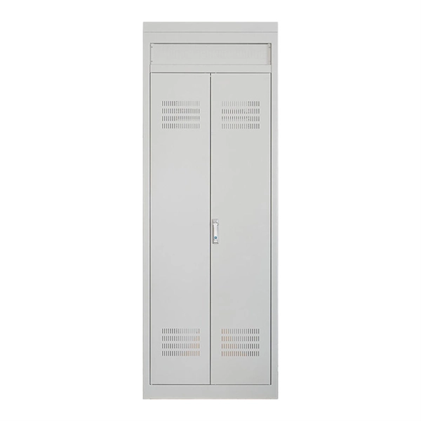
Please view our full RLH price list and contact us at info@fiberopticlink. com if you have any questions or special project needs. A Fiber Optic Patch Panel, also known as an Optical Distribution Frame (ODF) or fiber termination enclosure, is a centralized hardware unit designed to manage, protect, and organize fiber optic cable connections. In an era where data speeds and network reliability are non-negotiable, the patch. fiber optic patch panel, odf, optical distribution frame, fiber distribution panel, rack mount fiber patch panel, wall mount odf, fiber termination box, 1u fiber patch panel, 24 port fiber patch panel, 48 port fiber patch panel, outdoor fiber patch panel, fiber optic odf, sliding patch panel The. Q1: What is the difference between an ODF and a patch panel? An ODF is the entire frame or cabinet managing fiber connections, while a patch panel is a modular unit inside the ODF for cross-connecting fibers. Q2: How many fibers can an ODF handle? It depends on the ODF type; rack-mount units can. ODF is used in the terminal access link of FTTH system. It is a device that splices, distributes, and splits optical fibers and provides protection and management of optical fibers. Belden offers several Fiber Patching Systems. Full patching platforms include FX ECX for LAN environments, FX UHD for high-density fiber channels and the DCX System used primarily in data centers where high amounts of fiber connections and density are the key requirements, as in optical.
[PDF]

Learn how to identify and prevent these common issues. Installing a fiber optic patch panel may seem straightforward, but many network issues originate from small installation mistakes. Poor fiber routing, incorrect bend radius, or improper labeling can all lead to signal loss, maintenance difficulties, and unexpected downtime. This article highlights. What Can Go Wrong with Copper Patch Panels? What Can Go Wrong with Copper Patch Panels? Are you aware of the problems that a copper patch panel can cause in your network infrastructure? Learn how to identify and prevent these common issues. However, installation errors can lead to issues that impact network performance. This article offers guidance on proper installation and troubleshooting. Network patch panel, cable manager, network cable, wire stripper, crimping tool, zip ties. Use a small yellow tool or wire stripper to remove the outer jacket of the network cable. Cut off the cross-shaped skeleton of the Cat6 patch cord. Insert. Our guide delivers actionable, step-by-step best practices for rack layout, cable management, and patch panel installation. Many seasoned pros (and plenty of first-timers) run into avoidable pitfalls that turn a simple installation into a costly headache.
[PDF]

The Fiber Patch Panel, also known as a fiber distribution panel or fiber termination panel, serves as a central point for managing and organizing fiber optic cables within a network. What is a Fiber Patch Panel? Fiber optic patch panels are enclosures that act as a distribution hub for fiber cable. A bulk (multi-strand) fiber cable enters the patch panel and then each fiber strand is separated into individual strands or pairs of strands. These individual strands will then. A fiber patch panel is a mounted enclosure—either rack-mounted or wall-mounted—used to terminate, manage, and interconnect multiple fiber optic cables. It acts as a hub for organizing splices and patch cords, streamlining fiber management and preserving signal integrity. Cable Organization:. However, behind an organized fiber-optic network lies an unthinkable hardware device called a fiber patch panel. It helps you keep fiber optic cables neat in your network. You use this device to connect and separate fiber cables. It does not need power to work. Serving as the network's centralized junction, it provides secure ports for both incoming and outgoing. Learn what a fiber optic patch panel is, how it works, and why it is essential in modern fiber networks. A practical guide for FTTH, data centers, and telecom systems. In modern fiber optic networks, reliability, scalability, and ease of maintenance are just as important as transmission speed.
[PDF]
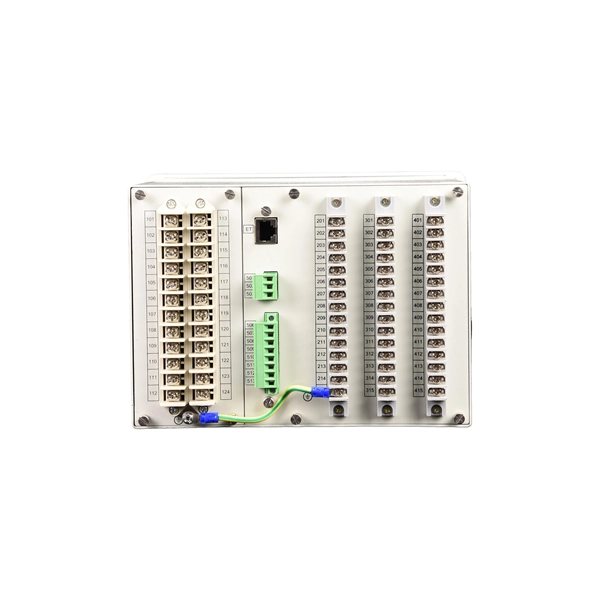
In an Ethernet patch panel diagram, each port on the patch panel is represented by a numbered or labeled square or circle. The diagram typically includes details such as the port numbers, cable types, and the devices connected to each port. Ethernet patch panel diagram is a visual representation of the connections between Ethernet cables and network devices, such as switches and routers. It provides a clear overview of how the network is structured, allowing network administrators to easily troubleshoot and manage the network. This information can be used to track the location of devices, their serial numbers, and their IP addresses. Change Management: Patch panel connection diagrams can be used to track. A patch panel is an essential component in a network system that provides a central location for connecting multiple devices or cables. The patch panel serves as. A pair of managed Gigabit Ethernet rack-mount switches, connected to the Ethernet ports on a few Panduit patch panels using Category 6 patch cables. (All equipment is installed in a standard 19-inch rack. Each port has a patch connection that links it to another port in another part of your building.
[PDF]

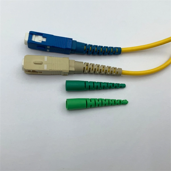
While most pigtails are single-fiber, multi-fiber options exist: Single-fiber: The most common (LC, SC, FC). Multi-fiber: 2, 4, 6, 12, 24, 48, or 72 fibers. Multi-fiber pigtails often come in ribbon format for splicing into high-count cables. Traditional Fusion Splice-On Connectors with pigtails provide factory-polished performance with field-termination convenience within harsh environments. Mass fusion splicing can fuse up to all 12 fibers in one ribbon at once. Mass Fusion Pigtails come with all 12 fibers terminated and a ribbonized. By fiber type, there are single-mode fiber optic pigtail and multimode fiber optic pigtail. And by fiber count, 6 fibers, 12 fibers optic pigtails can be found in the market. Fiber pigtails are used in an estimated 99% of single-mode fiber applications worldwide. Despite this ubiquity, they remain a source of confusion for procurement teams and junior installers alike—especially when it comes to connector type selection, polish type, and the tradeoffs between mechanical. Fiber optic pigtails can be divided into single-mode and multimode fibers. Conversely, multimode fiber pigtails, usually orange, use a 62. 5m to 2m—that has a factory-terminated connector on one end and bare fiber on the other end. The connector end is polished and tested under factory conditions, ensuring low insertion loss and high return loss.
[PDF]

Not all splitters are created equal. Here are the main types you'll encounter: The "1×N" notation indicates one input fiber and N output fibers. A 1×2 splitter divides the signal into two outputs, while a 1×8 splitter divides it into eight. The more splits, the. By dividing a single optical signal from a central Optical Line Terminal (OLT) into multiple outputs for Optical Network Terminals (ONTs) at users' homes, splitters eliminate the need for dedicated fibers to each residence—slashing infrastructure costs while scaling network reach. This guide. A fiber-optic splitter, also known as a beam splitter, is based on a quartz substrate of an integrated waveguide optical power distribution device, similar to a coaxial cable transmission system. The optical network system uses an optical signal coupled to the branch distribution. The fiber optic. Optical couplers can split or join signals in fibers. You can connect many users to one port with 1:n or 2:n splitters. These devices work both ways, which helps strong network communication. In a Passive Optical Network (PON), a single optical fiber carries massive amounts of data using light. They are named by the number of inputs and outputs, so a splitter with one input and 2 outputs is a 1X2, and a PON splitter with one input and 32 outputs is a 1X32.
[PDF]
In conclusion, choosing the right fiber optic connectors is an important decision that can have a significant impact on the performance and reliability of your fiber optic network. By considering the various factors.
[PDF]
Fiber optic couplers can either be passive or active devices. Passivefiber optic couplers are said to be passive as no power is required for operation. They are simple fiber optic components that are used to re.
[PDF]

Featured with transmitting and receiving signals over a single strand of fiber, 40G and 100G BiDi transceivers have emerged as a cost-effective solution for fiber optical cable utilization and data center deployment. These two BiDi transceivers will be described in. This guide explains how bidirectional communication works in the 100G Ethernet standard to effectively double the density of your existing fiber strands. Moving to 100GbE does not have to mean a complete infrastructure overhaul. Bidirectional fiber delivers multiple practical benefits to 100G. 100G BIDI QSFP28 optical transceiver uses the wavelengths of TX1304nm/RX1309nm with PAM4 signals for up to 40km transmission over single-mode fiber. The module supports 103. 25Gb/s with PAM4 lane signaling data rate with a simplex LC connector using the QSFP28 footprint. 25Gb/s electrical-to-optical. The Cisco 100GBASE Quad Small Form-Factor Pluggable (QSFP) portfolio offers customers a wide variety of high-density and low-power 100 Gigabit Ethernet connectivity options for data center, high-performance computing networks, enterprise core and distribution layers, and service provider. However, with multiple module types—such as SR4, LR4, CWDM4, and ZR4 —each optimized for different distances, fiber types, and network architectures, selecting the right 100G QSFP28 transceiver can be challenging. The module incorporates one channel optical signal and operates on 1271nm and 1331nm wavelength.
[PDF]

The primary function of a fiber adapter panel is to provide a housing for fiber optic adapters or connectors. These adapters act as the interface between the terminated fiber ends and the active equipment, such as switches, routers, or servers. A fiber patch panel is a mounted enclosure—either rack-mounted or wall-mounted—used to terminate, manage, and interconnect multiple fiber optic cables. It acts as a hub for organizing splices and patch cords, streamlining fiber management and preserving signal integrity. This guide will focus on elucidating the aspects of the fiber patch panel, its accessories, the work done with such a device, and how to. Fiber optic networks are the backbone of fast, reliable internet and modern communications, but even the best fiber cables need the right connectors and patch panels to work efficiently. Connectors are the points where fiber cables link to devices, equipment, or other cables, and using the right. The fiber optic patch panel, also known as the fiber distribution panel, serves as the crucial component of the management of fiber optic cables. Also, the advantage of fiber optic patch panels is to reduce the loss of fiber optic transmission and facilitate engineers to troubleshoot. Serving as the network's centralized junction, it provides secure ports for both incoming and outgoing fibers, streamlining connection.
[PDF]

A fiber patch panel is a mounted enclosure—either rack-mounted or wall-mounted—used to terminate, manage, and interconnect multiple fiber optic cables. It acts as a hub for organizing splices and patch cords, streamlining fiber management and preserving signal integrity. Cable Organization:. Structured cabling is a standardized system to help you organize and install the cables and hardware that connect your different devices to your network (including computers, servers, cameras, or any other smart gadgets). Structured cabling uses consistent components, such as patch panels, jacks. A fiber distribution panel is also called a fiber patch panel. It helps you keep fiber optic cables neat in your network. You use this device to connect and separate fiber cables. It does not need power to work. Serving as the network's centralized junction, it provides secure ports for both incoming and outgoing. Fiber optical patch panels can help data center management cables. Do you know which types are available? What are their functions? This article will show you. With the development of data centers, the cabling infrastructure is getting larger and larger, the patch panel gives the data center a. A patch panel, including fiber patch panels and Ethernet patch panels, is a passive network device that centralizes, terminates, and organizes multiple copper or fiber cables.
[PDF]
It is a device which either coalesces the luminosity signals from two PM fibers into a one PM fiber, or splits the light rays from the input PM fiber into multiple output PM fibers. Fiber optic couplers are optical devices that connect three or more fiber ends, dividing one input between two or more outputs, or combining two or more inputs into one output. The device allows the transmission of light waves through multiple paths. Fiber optic couplers can either be passive or. What are some common uses of fiber couplers in fiber optics, including fiber lasers? What are dichroic couplers and how are they used in fiber amplifiers? What is the principle of evanescent wave coupling? What factors influence the coupling strength and wavelength sensitivity in fiber couplers?. Fiber Optic Coupler is an optical cog that is capable of connecting single or multiple fiber ends in order to permit the broadcast of light waves in manifold paths. This optical device is also capable of coalescing two or more inputs into a single output while dividing a single input into two or. An optical fiber coupler is a device that splits light from one fiber into multiple fibers. There are different types of couplers classified by their shape, including Y, T, X, star, and tree couplers. Couplers work by transferring power between fibers through their cores or surfaces.
[PDF]
Our inspection and certification services cover: 1. general purpose containers 2. open top containers 3. reefer and thermal containers 4. swap bodies 5. offshore containers 6. portable units 7. tank containers 8.
[PDF]