This section includes all PoE enabled Industrial switches available, including managed models and specific application models like vehicle or substation compliant units. Check each product page for other buying options. Shop products from small business brands sold in Amazon's store. Learn more Need help? Industrial-grade PoE switches for demanding. POE Industrial Ethernet units at Plant Technology USA make Power over Ethernet solutions even more efficient and cost effective. Not only are these de. Read more Find the best Industrial Ethernet Equipment for your project. US-based Customer Support. These rugged, fanless platforms support both Gigabit and 10/100 Mbps Ethernet and offer a selection of fixed-fiber, or SFP uplink. We provide a wide range of PoE/PoE+/PoE++ switches with up to 90 W output per port to deliver high-speed data transmission while powering high-power devices over long distances. With an industrial-grade design, our PoE switches provide surge protection of 4 kV per LAN port. Additionally, Smart PoE. In addition to transmitting network data, a PoE Switch has a built-in Power over Ethernet injector to supply up to 100W Power over Ethernet (PoE) to standards-based 802. 3bt compliant devices such as IP cameras, VoIP phones, and wireless access points. When connecting network.
[PDF]

Appropriate Ethernet cables must be used to connect with the PoE and normal switch by means of a physical connection. Use the cables correctly and plug each end cable to the corresponding port on each switch to provide stable networking. So, the PoE switch is a networking device through which the PoE passes. In addition, this switch has numerous Ethernet ports that link to network segments, which also help with power and data. Can I use a PoE switch as a regular switch? (Answered) A POE switch gives power to devices that support the protocol, like cameras and access points. A regular switch, on the other hand, merely supplies the internet signal. A regular. A PoE switch simplifies network installation by providing power and data transmission over a single Ethernet cable. However, to take full advantage of a PoE switch, it's crucial to understand how to use it properly. This eliminates the need for separate power adapters, reducing cable clutter and. Just reuse teh POW cables that are alredy up there, and instead of them connecting to POE Wifi adapters, connect them to a POE switch (which would also allow me to add more cameras later) and drop a line from that switch into the main switch in the house. In this article we will uncover the subject matter of PoE switches and watch how they are necessary for the network design.
[PDF]

This diagram shows how the RJ45 cable is connected to the PoE switch, allowing it to power devices such as IP phones and cameras. In this article, we will explore the wiring diagram for a PoE switch, which provides a visual representation of how the switch connects to various devices. Each device is represented by a. Do you want to set up a new computer network in your home or office? Chances are, you'll need a Poe switch wiring diagram. Not only do these diagrams provide all the information you need to install a network, but they also help make the process easier and more efficient. For those who don't know. A PoE Switch, also known as Power over Ethernet Switch, is a network device that allows users to power and connect devices such as IP cameras, VoIP phones, and wireless access points. In essence, a PoE Switch can be described as regular switch with added ability of Power over Ethernet which allows. PoE technology enables the transmission of both data and power over a single ethernet cable, simplifying network setups and eliminating the need for additional power sources. This is particularly useful in scenarios where devices like IP cameras, wireless access points, or VoIP phones need to be. Here, you can see the details, Keep the copper strips towards your face and count the pin number or pin position from left to right. The T568B also has a total of eight pins and sight different colors.
[PDF]

Enable or disable the PoE function on S series switches: 1. system-view. Huawei's comprehensive portfolio of products and solutions enables you to realize smooth digital transformation and rapid growth of virtualization, Big Data, and cloud services. Huawei switches already help customers achieve success in industries such as finance, Internet, retail, education. Welcome to our user-contributed teardowns on the hottest new gadgets. You can write your own teardown, check out how others are contributing with their teardowns, and even check out disassembly photos and comprehensive hardware analysis. Why should I create a teardown? The Lenovo M910s has been. One of them in particular involves the use of Power-over-Ethernet (PoE), but as I don't already have any “standards-complaint” PoE equipment, I needed a cost-effective means of getting a workable set-up. In the early days of 100BASE-TX Ethernet, only two of four pairs of the Ethernet cable were. If one or multiple PoE chips of a PSE are suspended, the port connected to a PD cannot detect the suspension and fails to power the PD. In this case, you can reset the PoE chip. The PoE chip is reset. If PoE power modules are working normally, check whether the PoE card and DIMM are working normally. If the register. Only electrical interfaces of switch models with PWR or PWH in the device names support the PoE function. All views Before using the PoE function, run the display poe device command to check.
[PDF]
Follow these steps to connect your WiFi router or modem using the TP-Link TL-POE10R POE Splitter: Plug one end of a Cat6 Ethernet cable into a POE port on the POE switch. This cable will carry both data and power. Connect the other end to the Ethernet input port of the TP-Link POE. We can use TL-POE150S and TL-POE10R to expand the network for the place where power line can not reach or there is no outlet. In the topology shown as above, both TL-POE10R and the device which connect to it do not need external power adapter, the TL-POE150S can provide power supply and data for. In this video, we dive into how to use the TP-Link TL-POE10R POE Splitter to supply power and LAN connectivity to a WiFi router, modem, or access point from a CCTV system POE switch. This powerful device simplifies your network setup by delivering both power and data through a single Ethernet. Connecting TP-Link cameras to a POE switch is a seamless, plug-and-play process that powers and networks your security system in minutes. Simply link the camera to the POE switch using a single Ethernet cable—handling both data and power—then configure via the TP-Link app for live viewing and. The Injector sends power and data over the Ethernet cable to the Splitter. Then the Splitter separates the data and power back into two cables and delivers them to the remotely located access point or other network device that requires a 5/9/12-volt power input. 2 Features Complies with IEEE.
[PDF]
Let us now see the differences between PoE and Non-PoE Switch. We will take some important parameters and list out the differences. Before understanding PoE, let us quickly take a look at a Network Switch. An Ethernet Switch or a Network Switch is a device that has several RJ45 Portsto connect many devices. The switch will transmit data between ports using the destination MAC Address in the Ethernet Frame. If you consider the OSI Model, Switches are Layer 2 or Data Link Layer d. Now that we have seen the differences between PoE and Non-PoE Switch, the question is which one should you buy? Assume your devices are all non-PoE i.e., computers, laptops, and other networking devices with power supply. In this, you are better off with a regular non-PoE Switch. You can save a lot on the switch but in our frank opinion, this is no.
[PDF]

6Wresearch actively monitors the Brunei Industrial Ethernet Switches Market and publishes its comprehensive annual report, highlighting emerging trends, growth drivers, revenue analysis, and forecast outlook. Fixed configuration switches offer ethernet switching solutions for various applications, including campus, midsize businesses, enterprise branch offices, and small and medium-sized businesses (SMBs). These switches also provide access security, sustainability, operations excellence, and improved. With 10 or 40 Gigabit Ethernet access ports and a high throughput backbone, FortiSwitch Data Center Switches are ideal for top-of-rack server or firewall-aggregation applications. These high-speed switches are also well suited for enterprise network core or backbone network installations. Our. Industrial Ethernet switches Ethernet devices designed for harsh industrial environments deployment that are prone to shocks, vibrations, and extreme temperatures. These switches come in two types, managed and unmanaged offer Gigabit, and PoE capabilities with various industry certifications. The Ethernet Switch Market Report is Segmented by Switch Type (Fixed Configuration, Modular, Rugged/Industrial, Virtual/Software-Defined), Port Speed (1G and Below, 2. 5G/5G, and More), End User (Data Centers, Telecom, Enterprise, SMB, and Industrial/IoT), Switching Technology (Layer 2, Layer 3.
[PDF]
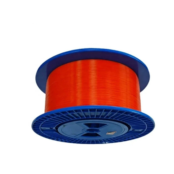
Professional quotes from experienced fiber optic cable installation contractors are crucial for accurate project estimates, as the costs of fiber optic cabling can vary significantly based on location, terrain,.
[PDF]
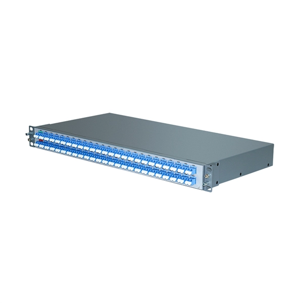
The SFP port is commonly found on Gigabit Ethernet switches and is primarily used for fiber optic device connections or for uplinking 1G switches to aggregation/core layer devices, providing higher-bandwidth links. You can add a compatible SFP transceiver module to the SFP port of. SFP ports enable Gigabit switches to connect to a variety of fiber and Ethernet cables and extend switching functionality throughout the network. Small form-factor pluggable is a hot-swappable interface used to connect network and storage switches and transfer data. Switches with SFP ports can. Choose an SFP module based on the fiber optic cabling that will be connected to the network switches. SFP transceiver modules almost always require two fiber optic cable strands. In this guide, we'll cover the following: What is an SFP port? Why is the SFP port important? SFP vs. QSFP28. Enterprise LANs use the RJ45 port on 100/1000BASE switches. It connects access layer devices and uplinks from desktop switches or directly to end devices. RJ45 ports remain essential for. An SFP switch uses Small Form-Factor Pluggable (SFP) modules to form a network switch for high-speed connectivity between devices. These interchangeable modules support various media types, including copper or fiber-optic cables, providing flexible networking options based on specific requirements.
[PDF]
Some routers have an embedded switch (some of the interfaces act as layer 2 switch ports). This would allow each switch to communicate with the router and. The main use of the network is to provide internet access to the various clients on our site, the diagram only shows the core distribution layer. I have added R2 as a second internet connection for fallback/bandwidth benefits. Clearly, this means 2 default gateways, 2 DHCP servers, etc but my. A dual-WAN router/gateway can connect two separate internet connections at the same time. A dual-WAN gateway works in two operating modes: failover and load balancing. In failover mode, the primary ISP will be active all. I want to connect an L3 switch ( Tp-Link T1600-28PS)with two different gateways. One is the Comcast voice edge and the other is the ISP. So in every port to be able to connect an IP phone and a PC and respective packed to be routed to the proper gateway. However, the gateway acts as an intermediary. This article describes the connectivity issues that occur when multiple default gateways are used in TCP/IP configuration options.
[PDF]
Step 3 Remove the cables or optical modules from the old card. Press the two green locking clips in the middle of the card to eject the ejector levers. Turn the ejector levers outward and slowly pull the card out. Place the replaced. Unplug the optical fibers from the optical module before removing it. Install or remove optical fibers carefully to avoid damaging the fiber connectors. If an optical module cannot be completely inserted into an optical. Page 7 Optical port USB storage device Wi-Fi terminal 1. Wear an ESD wrist strap or ESD gloves when replacing the optical module. Therefore, replace an optical module only when you confirm.
[PDF]
5G, and 10G speeds for flexible customization, ensuring optimal performance, compatibility, and scalability Flexible interface options like copper, fiber, and PoE ensure seamless integration and cost-effective deployment. Provides 1G, 2. The Pro Aggregation does this with it's SFP28 25Gbps ports. The regular Aggregation switch is best used to connect all devices in a rack. Layer 3 stackable access and aggregation switches with Multi-Gigabit Ethernet, High Power PoE, and up to 100G. New 1G option is optimized for IoT density. So, I have tried messing with VLANs, I've tried LAG, but I can' seem to get traffic to.
[PDF]
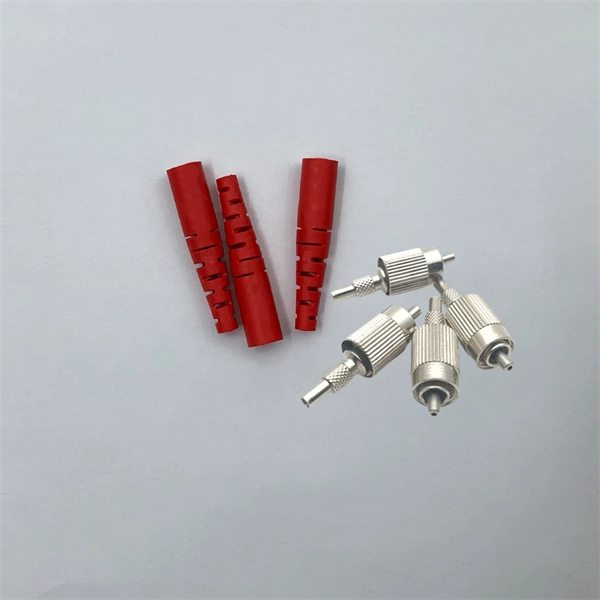
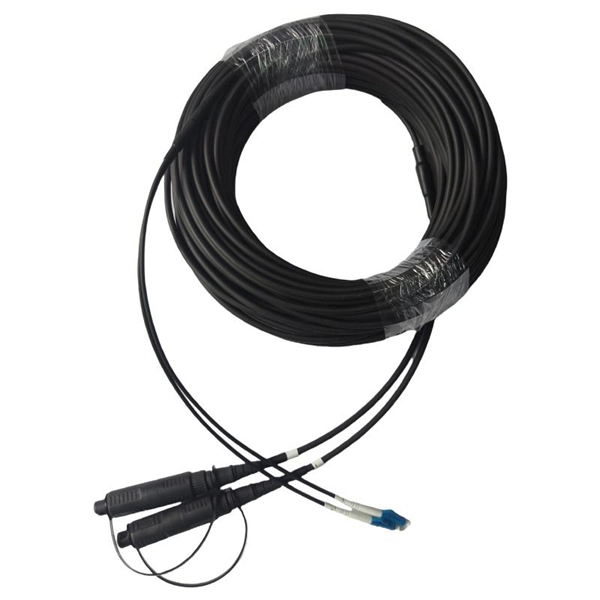
Connect the fiber optic cable: Attach the fiber optic cable's connector to the transceiver module on the switch. Make sure the connector type (e., SC, LC) matches the transceiver module. Fiber optic cabling is increasingly used to connect network switches and other datacom equipment, especially in long-distance and mission-critical applications. Fiber provides: Increased internet signal bandwidth. Most modern fiber-enabled network switches require an SFP transceiver module. This document describes how to troubleshoot fiber optic interfaces by addressing some of the fiber optic module and cabling specifications. There are no specific requirements for this document. The information in this document is based on all Catalyst 9000 Series switches. This includes Doppler. Connecting a switch to a fiber optic network involves several steps and requires specific equipment to ensure a successful and efficient connection. If you're looking to learn how to configure fiber optics on a Cisco switch, it's important to first configure the switch settings so it's ready for fiber optics. Fiber optic switches utilize. Other than entry level network switches, most of today's network switches include one or more GiBC (Gigabit Converter) or SFP (Small Form-factor Pluggable) slots. SFP modules insert into these slots and and require two strands of fiber, typically duplex Using multi mode fiber (for runs under 1000.
[PDF]

Optical switches will accept inputs nearly immediately as compared to mechanical switches, which could experience a few milliseconds of debouncing lag. Since optical switches do not depend on physical contact, input latency (latency) is severely minimized. This discrepancy can just be a couple of. An optical transistor, also known as photonic transistor, optical switch or light valve, is a device that switches or amplifies optical signals. Any communication protocol (Ethernet, ATM, etc. Significant. High Speed: Optical switches provide a high-speed data transmission capacity that surpasses that of traditional electrical switches. Interference Resistance: They are immune to electromagnetic interference, ensuring a reliable data transfer. Low Power Consumption: With no need for O-E-O conversion. Optical switching is the process of controlling the destination of individual optical information signals. This technology allows for high bit rate transmission to be switched between various optical lines. The core component enabling optical switching is the Optical Switch. Figure: Optical Switch. Serving as the backbone of high-speed fiber-optic networks, data centers, and emerging technologies like quantum communication, optical switches enable efficient light signal management with a small latency. As global demand for bandwidth surges due to 5G, AI, and cloud computing, advancements in.
[PDF]

Are the protection parameters set correctly (trip value, trip time)? Is the assigned protection function blocked? Is the protection function´s trip signal routed to the Trip-Manager of the correct switchgear? Is the trip signal of the switchgear . Are the protection parameters set correctly (trip value, trip time)? Is the assigned protection function blocked? Is the protection function´s trip signal routed to the Trip-Manager of the correct switchgear? Is the trip signal of the switchgear . Master trip relay or lockout relay, also known by ANSI code 86, holds a significant position as an intermediator between the protection relay and control points, even though it is not self-equipped with fault sensing capabilities. The master trip relay can operate as a hub of multiple protection. Since protection relays can be expensive, it is not advisable to connect them directly to the trip coil. if the fault detected by any of the protection relay means at the same time the protection relay trips the associated circuit breaker through the mater tripping relay circuits. Master trip relay is not a monitoring relay. It. After first start-up of the protective device there is a pending trip. Two red LEDs are illuminated at the front of the HMI. It typically refers to the time duration taken a.
[PDF]