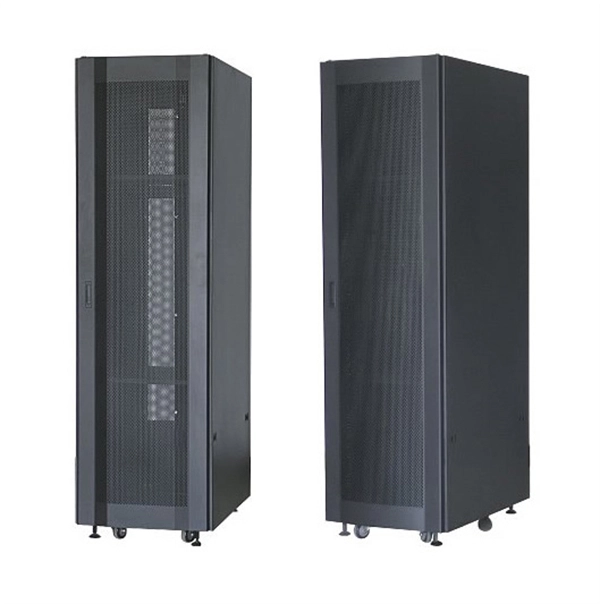
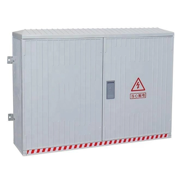
The residential electricity price in Uzbekistan is UZS 590. 000 per kWh or USD 0. These retail prices were collected in September 2025 and include the cost of power, distribution and transmission, and all taxes. Auxiliary needs cabinets SHE 8350 (analog PSN 1100) (Cabinets for input and distribution of electrical energy). Electrical equipment and materials play a key role in modern industry and the household sector. Our website features products from various suppliers, allowing you to choose the most. In February 2025, the average electricity supply meter import price amounted to $59. 6 per unit, almost unchanged from the previous month. Over the period under review, the import price recorded a sharp contraction. From January 2025. Comprehensive selection, installation and configuration of equipment for your business Optimize production with modern solutions of Instrumentation and Automation! We have a wide selection of instrumentation and automation products and electrical goods from leading manufacturers. Overall, consumption, however, continues to indicate a noticeable decrease. As a result, consumption attained the peak level of $X. The Uzbekistan Electricity Meters Market is projected to witness mixed growth rate patterns during 2025 to 2029. Beginning strongly at 11. 75% in 2025, growth softens to 11.
[PDF]
At higher altitudes, factors such as decreased air density, temperature variations, and reduced cooling efficiency can affect the electrical resistance of conductors, leading to potential power losses and reduced system performance. As electrical systems are deployed at various elevations, it becomes essential to understand the potential failures that can occur due to altitude-related factors. In this blog post, we will explore the effects of altitude on electrical equipment based on our experience Photovoltaic Research Base. As power lines are often located at varying elevations, understanding how altitude impacts conductor performance is crucial for optimizing transmission efficiency. Altitude Is A Crucial Factor That Can Significantly Impact The Performance And Reliability Of Electrical Equipment (symbol Image: CLOU) Altitude is a crucial. Heat Dissipation Challenges: Lower air density at altitude significantly reduces the effectiveness of convective cooling. Cables carrying current generate heat (I²R losses). With reduced cooling capability, cables can operate at significantly higher temperatures than at sea level, even for the. Transformers and switchgear get derated at high altitudes, but I have not seen it done for cables.
[PDF]
Step-by-step guidance on installing an electric meter box safely—site prep, clearances, mounting height, wiring, grounding, permits, and code compliance explained. 11 When Should You Hire a Licensed Electrician for Meter Box Installation? What Is an Electric Meter Box and What Does It Do? An electric meter box (often called a meter enclosure or meter socket) is the enclosure that holds the meter socket and supports the utility meter that measures energy use. Learn safety tips, wiring steps, troubleshooting, and when to call a pro. An electric meter box measures how much electricity your home uses. It helps the utility company give you the right bill. If you're setting up a new one or replacing an. In this guide, we will break down the key elements involved in connecting the main power supply to your home, providing a clear path for a successful setup. We will focus on the critical parts of the system, from basic components to step-by-step assembly procedures. Installing an electric meter box might seem like a job for professionals only—but with the right knowledge, it's a task many homeowners. Limited the meter location from pad mount transformer for PSO. Removed unistrut being listed as an alternative means for mounting the meter box. APCo and TX do not allow unistrut for installations. 7/2020 Revised Figure 15. Added wording for consistency with Section 8 of document.
[PDF]
Fusion splicing is most widely used as it provides for the lowest loss and least reflectance, as well as providing the most reliable joint. Virtually all singlemode splices are fusion. 📦 For purchasing, use the RP Photonics Buyer's Guide for fiber cleavers. It provides an expert-curated supplier directory, buyer-focused technical background information, and structured selection criteria to support professional procurement decisions. In many applications of fiber optics, it is. The fiber optic quick connector/cold connector is a very innovative field-terminated connector, which contains factory-installed optical fiber, pre-polished ceramic ferrule and a mechanical splicing mechanism. The incoming optical fiber or indoor optical fiber can be inserted into the mechanical. A reliable fiber-optic network depends on more than selecting the right cable and connectors; it hinges on the quality of every splice. In fact the splice shall ensure high quality and stability of performance with time. Either joining method must have three primary characteristics. Fiber joints are the points where two optical fibers are permanently connected to create an uninterrupted transmission path. These connections are essential in fiber optic networks, enabling the extension, branching, or repair of fiber cables while ensuring minimal signal loss during transmission.
[PDF]
When selecting the right fiber optic splice tray, prioritize compatibility with your cable type, secure fiber management, and ease of installation. Corning splice trays offer an easy way to store fiber optic cables and splices while protecting them from damage during fusion and mechanical splicing. The trays are engineered to use with both loose tube and tight-buffered optical cables. Their generous size and craft-friendly design help prevent. Fibre optic splicing trays are an essential part of manipulating and ordering optical fibers inside a network structure. Since the need for higher data rates and effective communication gets more robust, the utilization of optical fibers has become increasingly widespread across multiple spheres of. Optical / fiber optic 12 or 24 fiber splice tray for holding spliced fibers of fiber optic cable. For most network installations—especially in data centers or FTTH (Fiber-to-the-Home) deployments—a modular, stackable splice tray with 12 to 24 port. Discover CommScope fiber splice trays, fiber optic splice trays, and a convenient fiber splice organizer. Organize fiber connections with ease. Because optical fibers are sensitive to pulling, bending, and crushing forces, use fiber splice trays to provide secure routing and an easy-to-manage environment for fragile fiber splices. In the past, fiber optic splice trays were usually installed in a box that hung on the wall.
[PDF]

This guide will walk you through the process of checking photo sensors using a multimeter, covering various types of photo sensors, the necessary tools and safety precautions, and the specific measurement techniques involved. Knowing how to effectively use a multimeter to test photo sensors can save you time, money, and frustration when dealing with malfunctioning devices. more What is a Voltage Divider? | What is a Voltage. Before replacing the sensor or fixture, it's efficient testing it first, With a few tools and a step-by-step process you can find whether your outdoor lighting control system is working as intended or if the problem lies elsewhere. In this complete guide from Lead-Top, a global leader in photocell. In this blog post, we explain step-by-step how to troubleshoot a sensor with a digital multimeter (DMM). Here are the steps: Troubleshooting a sensor measurement failure requires mechanical tools to uncover the protective shields or components so you can reach the sensor in question. Always follow the manufacturer's instructions for the sensor and multimeter. Ensure the sensor is properly connected to the multimeter and. A multimeter is an indispensable diagnostic tool for anyone working with electronics, electrical systems, or indeed, sensors. It's a versatile device capable of measuring voltage, current, and resistance, providing crucial insights into the health and functionality of electrical circuits and.
[PDF]
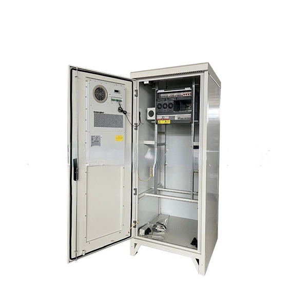
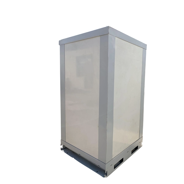
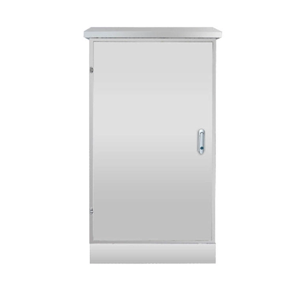
These products are highly integrated, compact in size, structurally compact, safe and reliable in operation, easy to maintain, and portable. In distribution systems, they can be used in ring network distribution systems as well as in dual power supply or radial terminal distribution. High voltage and low voltage complete sets occupy a significant place in modern electrical engineering as they are responsible for safe, secure, and efficient power distribution to all types of industries. They are known as complete switchgear assemblies because they integrate inside them such. Electricity plays a critical role in ensuring national well-being and livelihoods, and the stable development of the power industry drives socio-economic progress. To achieve structural adjustment and transformation in the power industry, the foremost priority is enhancing the performance of. Our high and low voltage complete electrical equipment solutions are designed based on a deep understanding of the current development trends in the power industry and accurate predictions of future power demand. It is mainly used to protect, control and isolate electrical equipment. Its primary functions are to cut off the power supply of equipment to facilitate subsequent maintenance. Senior Electrical Engineer, with 12 years of experience in high and low voltage switchgear installation, commissioning, and overseas project technical support. Currently, Thor is the Technical Department Manager at Weisho Electric Co.
[PDF]

In modern FTTH architectures, the ODN is the physical fiber layer that distributes optical signals from the central office to end users. Operators consider ODN design as one of the most important factors affecting: Network coverage Optical loss performance Deployment cost. This passive layer is known as the Optical Distribution Network (ODN). Its role is to provide an optical transmission channel between the OLT and the ONU. The ODN network design is a physical facility that connects the communication room and user equipment, and is a key component. Short summary: The Optical Distribution Network (ODN) is the passive infrastructure linking the central office to the subscriber in FTTH. This guide delves into essential ODN components like splitters, distribution boxes, and ODFs, showcasing how Hainan ZTO Cable Co. It's the silent, robust highway that delivers blazing-fast Fiber-to-the-Home (FTTH) and 5G services. The maximum permissible optical power attenuation between OLT optical ports to ONT input is 28dB, which is by utilizing the so-called Class B optical network. At the heart of every Fiber-to-the-Home (FTTH) deployment lies the Optical Distribution Network (ODN) — a meticulously engineered passive infrastructure that enables operators to deliver massive bandwidth, low latency, and reliable service to millions of users. The ODN connects the Optical Line.
[PDF]

These regulations may be called Bangladesh Energy Regulatory Commission (Electricity Grid Code) Regulations, 2018 or in short Grid Code. These regulations shall come into force from the date of publication in the official gazette. INTRODUCTION. Title. “Schedule” means the schedule of these Regulations. The Grid Code shall apply in the field of electricity transmission system planning, connection conditions. Bangladesh Energy Regulatory Commission ELECTRICITY GRID CODE 2019 Effective Date: March _ _, 2019 Electricity Grid Code 2019 Bangladesh Energy Regulatory Commission NOTIFICATION Dated: March _ _, 2019 In exercise of the powers conferred by section 59 of the Bangladesh Energy Regulatory Commission. These regulations may be called Bangladesh Energy Regulatory Commission (Electricity Grid Code) Regulations, 2018 or in short Grid Code. INTRODUCTION In exercise. Wherever you are, BANGLAMARK is your reliable partner for the one-stop planning and construction of customized, state-of-the-art high-voltage substations. For power grid operators and utility companies the reliability of their power transmission and distribution equipment installed in their network.
[PDF]
Plugs directly into Polaris Pulse System for switch lighting and keyed on ignition. Made in the USA! Activates High current relay when High Beams are turned on, used to add large light bars and driving lights without having to install additional switches in the dash. Made in the USA!. $ 46. 00 Original price was: $46. Upgrade your Polaris with the XTC Power.
[PDF]
The formula to calculate the cable tray capacity is: [ CTC = text {floor}left (frac {W cdot H cdot FR} {CA}right) ] Where: ( CTC ) is the cable tray capacity (number of cables). ( W ) is the width of the cable tray (inches). ( H ) is the height of. This calculator determines the maximum number of cables that can be safely housed within a cable tray based on its dimensions and the cross-sectional area of the cables. Properly calculating cable tray capacity is crucial for ensuring efficient airflow, preventing overheating, and maintaining. Calculate the appropriate cable tray size based on your cables and fill requirements. This calculator determines if your tray meets industry standards (typically 30-50% fill for alternating single-layer or 40-50% for random arrangement). ( FR. The right cable tray sizing calculator helps engineers turn cable schedules into a verified tray width and fill check before material ordering and site installation. IEC 61537 covers cable tray and cable ladder systems for the support and accommodation of cables, while NEC Article 392 governs cable. In practice, cable tray dimensions are a system of interrelated measurements —width, depth, length, and material thickness—that directly affect cable fill compliance, heat dissipation, structural loading, and long-term expandability.
[PDF]

Recommendation ITU-T L. 12 specifies splices of single-mode and multimode optical fibres. It describes suitable procedures for splicing that should be carefully followed in order to obtain reliable splices between single optical fibres or ribbons. Typical applications of these methods include aerial, buried, and underground splices. (2) American National Standard Institute/National Fire Protection Association (ANSI/NFPA) 70, 1993. § 1755. 370 - RUS specification for seven wire galvanized steel strand. 400 - RUS standard for. ation or liability to users of this publication. Existence of a standard shall not preclude any member or nonmember of NECA or FOA from specifying or using alternate construc Code (NEC) in effect at the time of publication. Because they are quality standards, NEIS® may in some instanc s go beyond. RUS standard for splicing copper and fiber optic cables. (FOA) was founded in 1995 to help develop the workforce to build the fiber optic networks to support a rapid expansion in communications and the Internet. The charter of the FOA was to promote professionalism in fiber optics through education, certification, and.
[PDF]

Optical cable lines lightning protection and strong current protection are achieved by avoiding, guiding or discharging them underground to prevent lightning and strong current from causing damage to the optical cable lines themselves, communication equipment and personnel. Since the lightning. ntly, there are a limited number of industry documents that address the requirements for optical fiber cables near high voltage circuits. One standard that has been developed by the Institute of Electrical and Electronics Enginee s, Inc (IEEE) is 1222, “IEEE Standard for All-Dielectric. The Fiber Optic Association, Inc. (FOA) was founded in 1995 to help develop the workforce to build the fiber optic networks to support a rapid expansion in communications and the Internet. ” It defines the requirements for ADSS cables placed aerially in a high. This Recommendation provides a procedure to protect the telecommunication lines using fibre optics against direct lightning discharges to the line itself or to the structures that the line enters. The protection procedure is related to the exposure of the line to direct lightning discharges and. Armored Cable: For direct burial or areas prone to crushing, use armored fiber optic cables that have an additional layer of metallic or non-metallic protective sheathing. Cable Trays and Ladders: In data centers and industrial settings, use cable trays or ladders to support runs, keeping them off.
[PDF]
In this blog, we will explore the step-by-step process of using a beamsplitter cube effectively, along with some common applications that benefit from this powerful optical tool. Step-by-Step Guide on Using a Beamsplitter Cube. 📦 For purchasing, use the RP Photonics Buyer's Guide for beam splitters. It provides an expert-curated supplier directory, buyer-focused technical background information, and structured selection criteria to support professional procurement decisions. What are Beam Splitters? A beam splitter (or. An Optical Beamsplitter is an optic or optical device that is used to split a beam of light in two. Newport offers a wide variety of Beamsplitters in various shapes. It is a crucial part of many optical experimental and measurement systems, such as interferometers, also finding widespread application in fibre optic telecommunications. One beam is typically reflected while the other is transmitted. The ratio of reflected to transmitted light can vary based on the design of the beam splitter. Our plate beamsplitters have a coated front surface that determines the beam splitting ratio while the back surface is wedged and AR coated in order to minimize ghosting and interference effects.
[PDF]

GOOD WILL INSTRUMENT (SUZHOU) CO. Browse online or download User Manual for Equipment Gw-instek GOS-652G. GW Instek GOS-652G User Manual 50MHz Cursor Readout With Delayed Sweep.. GOS-658G 20MHz Cursor Readout... GOS-652G 35MHz. Caution statements identify conditions or practices that could result in damage to this product or other property. THIS APPLIANCE MUST BE the letter E or by the earth symbol or coloured Green or Green & Yellow. EARTHED The wire which is coloured Blue must be connected to the terminal which is. y have a fraction of the total loss compared to fiber-based equivalents. FBG also provides a latency in the o der of nanoseconds as compared to microseconds in fiber-based solutions. The FBG based DCMs are designed to perfectly mimi the dispersion and dispersion slope characteristic of G. 652 fiber. g sensitivity and low water-peak level. Together they allow unlimited use of the whole telecom wavelength win ow for a great variety of applications.. GOS-653G Basic... GOS-622G. The GOS-653G/652G Series is an example of classic analog oscilloscope design. The GOS-653G /652G cover a broad range of industry applications, such as product design, assembly lines, repair & servicing, and educational purposes for EE laboratories and class experiments. Coupled with various trigger.
[PDF]