Microprocessor-based solid-state digital protection relays now emulate the original devices, as well as providing types of protection and supervision impractical with electromechanical relays.OverviewIn, a protective relay is a device designed to trip a when a is detected. The first protective relays were electromagnetic devices, relying on coils operating on moving par. Electromechanical protective relays operate by either, or. Unlike switching type electromechanical with fixed and usually ill-defined operating voltage thresholds. Electromechanical relays can be classified into several different types as follows: "Armature"-type relays have a pivoted lever supported on a hinge or knife-edge pivot, which carries a moving contact. These relays may.
[PDF]

This handbook covers the code of practice in protection circuitry including standard lead and device numbers, mode of connections at terminal strips, colour codes in multicore cables, dos and donts in execution. Also principles of various protective relays and schemes including special protection. Read this document and the documents listed in the additional resources section about installation, configuration, and operation of this equipment before you install, configure, operate, or maintain this product. Users are required to familiarize themselves with installation and wiring instructions. presentation of protection and control relaying. The report will identify methodology behind these practices, present issues raised by the integration of microprocessor relays and the internal logic and external communication configurations, ying. The objective of this presentation is to convey a basic understanding of protective relays to an audience of engineers already familiar with low voltage protective device coordination. HT panel protection relay. The HT power supply is received from GO switch and distributed to the. The handbook for protection engineers includes guidelines on protective circuitry, protective relay principles, and testing procedures for switchgear and relays. It covers standard codes, wiring practices, and norms for protecting generators, transformers, and lines, and provides detailed.
[PDF]

This article describes the anti-pumping relay, its definition, function, and circuit diagram. In a circuit breaker it is desired that when close and trip operation is performed on the circuit breaker with the closing coil energized, the subsequent closing operation should be prevented. So let's. Anti-Pumping relay is nothing but a NO contact, which means when the circuit breaker in closed condition the relay will be as NO point and if the circuit breaker in open condition the relay will be as NC Condition. The anti-pumping relays is connected in series with the circuit. An anti pumping relay (also called antipumping relay or Y-relay and ANSI 94 Trip or Trip-Free Relay) is a protective device that prevents a circuit breaker from closing repeatedly when a continuous close command is present. In simple terms, it stops your circuit breaker from “pumping” – which means. Anti-pumping relays are used in circuit breakers to prevent the breaker from closing unexpectedly after tripping. If the TNC switch fails (Trip normal close) or there is any problem with the CB (circuit breakers) closing circuit, the continuous CB (circuit breakers) close command can be extended to. Why is the Anti-Pumping Relay Used? A circuit breaker is a very important equipment for a high-voltage power system. It protects the system from high current or voltage during a faulty condition.
[PDF]

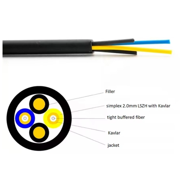
Plug an SEL-2810 Fiber-Optic Transceiver With IRIG-B directly into a standard 9-pin serial connector (DB-9). No special mounting is required. The SEL-2810 receives power from the host device via the connector; no separate power supply or power wiring is needed. It also requires no. Improve safety, signal integrity, and reliability by using optical fiber instead of wire for instrumentation, protection, automation and other applications that benefit from economical fiber-optic links up to ½ kilometer long. Fiber-Optic Link— Establish EIA-232 communication between devices over a. The RLH Contact Closure Fiber optic converter transmits 8 digital input signals over fiber optic cable. Applications include alarm event triggering, building automation, environmental control systems, fire & alarm systems, gate control, traffic signal control equipment, and more. Use two optical fibers instead of 32 wires between outdoor or remote equipment and the control building to reduce costs, improve safety, and boost reliability. SFP transceivers bridge electrical and optical signals, making them indispensable in data centers, telecom networks, and.
[PDF]

To provide effective and reliable protection to the power system, a protective relay must have the following essential functional characteristics: Selective, Fast, Stable, Reliability, Sensitivity, Simple Construction and Installation Mechanism, and Cost-effective. Characteristics of Protective Relay elements using different operating principles. These principles and design criteria determine how well the basic function is performed and how in practice it deviates from the ideal. These are some essentially. What is a Protective Relay? – Functions, Types & Applications Reliability and safety are paramount in the vast and intricate power systems world. Enter the protective relay, a crucial device designed to detect and respond to abnormal conditions, faults, and disturbances in electrical networks. Types of Protective Relays: Protective relays are categorized by their mechanism (electromagnetic, static, mechanical) and function. A protection relay is a crucial component of electrical systems that safeguard infrastructure, employees, and equipment from electric problems and malfunctions. It functions as a watchdog by constantly surveying multiple system components including voltage, current, frequency, and phase angle. Based on Operating Principle Electromechanical Relays: Work using moving parts and electromagnetic forces (traditional.
[PDF]

Arduino Safety Relay Box With Wall Socket : A relay is an electrically operated switch. In this project there is no real need to isolate one circuit. Relay rooms are essential in modern commercial or industrial buildings, serving as secure enclosures for electrical relays that manage power distribution and automation systems. Designing a relay room requires balancing technical precision with safety, efficiency, and future scalability. Many relays use an electromagnet to mechanically operate the switch and provide electrical isolation between two circuits. In this article, you will learn how to design an electrical control cabinet for optimal safety and efficiency, following some. This handbook covers the code of practice in protection circuitry including standard lead and device numbers, mode of connections at terminal strips, colour codes in multicore cables, dos and donts in execution. Reliable components ensure system faultlessness and durability. Modern design and user-friendliness. equipment of most. This is Part 1 in a series of tutorials that will show you how to build a Bussmann RTMR fuse/relay block. If you're not familiar with this product, it's a simple waterproof enclosure that allows you to connect accessories on your vehicle through relays and/or fuses. After reading this tutorial, you.
[PDF]

Optical modules convert electrical signals into light to move data quickly and reliably in AI systems, enabling fast and smooth data processing. Using advanced optical modules boosts AI system speed and bandwidth, helping handle large data loads with low delay and high efficiency. Optical modules. Laboratory utilities: framework for communication with laboratory equipment and post-processing of data (opticomlib. You can install opticomlib using pip: or from source code: NumPy Compatibility: binary_sequence and electrical_signal now fully support NumPy protocols, allowing direct use with. The optical module serves as a crucial component in optical fiber communication systems, operating at the physical layer, which is the lowest layer in the OSI model. Its primary function is to achieve optoelectronic conversion by converting electrical signals into optical signals and vice versa. An. Learn about the components inside a coherent optical engine, what they do, and how they use modulation to send and receive data. Optical communications over metro, long-haul, and submarine networks once used simple direct-detect technology. That's no longer the case.
[PDF]
Main distribution boards (MDB) manage and distribute electrical power from one or more sources to branch circuits in an LV distribution system. It provides circuit breakers for each branch circuit to prevent faults and incidents. Panelboards are designed to meet UL 67 and NEMA Standard PB1. What is the difference between a switchboard and a panelboard? Switchboards and panelboards provide a similar functionality in a power distribution system. Panelboards are typically flush mounted or surface mounted and are limited to a. A distribution board (also known as panelboard, circuit breaker panel, breaker panel, circuit breaker, electric panel, fuse box or DB box) is a component of an electricity supply system that divides an electrical power feed into subsidiary circuits while providing a protective fuse or circuit. According to NEC Article 100, branch circuits are the conductors between the final overcurrent device protecting the circuit and the outlet. This article deals with lighting and appliance branch circuits. The article also covers motors or. A panelboard is a distribution assembly designed to divide an incoming electrical feed into numerous smaller branch circuits. Each circuit is protected by its own circuit breaker. Inside a distribution box are components. multiwire). Branch device and terminates at another circuits are usually low current (30 amps or distribution center, panelboard, or load less), but can also supply high curre ts.
[PDF]

Generator protection relays are devices that detect abnormal operating conditions and isolate the generator from the system to prevent damage. These relays act as the first line of defense and are installed with strict adherence to IEC Standard for Protection Relays. Protecting generators from different electrical, mechanical, and thermal stresses is known as generator protection. To safeguard machines from overloads and unusual circumstances, preventive measures are required. Faults are inevitable even with effective design, construction, and operation. Below is an overview of the different types of relays used in generator systems, their functions, and their specific applications. Electromagnetic relays use. Generator Protections are broadly classified into three types: Class A, B and C. Class A covers all electrical protections for faults within the generating unit in which generator field breaker, generator breaker and turbine should be tripped. What Are Generator Protection Relays? Generator protection. There are various protection relays and those are used for protection against a wide variety of conditions. The fundamental principles that are covered in this course are equally applicable to. IEEE C37. 2 defines the IEEE “numerical” function designation for all protective relay functions. This presentation primarily uses the designations from the Beckwith M-3425A relay, which in most cases follows IEEE C37.
[PDF]
A grid networks consist of an interconnected grid of circuits, energized from several primary feeders through distribution transformers at multiple locations. Grid networks are typically featured in.
[PDF]

This guide will walk you through the process of checking photo sensors using a multimeter, covering various types of photo sensors, the necessary tools and safety precautions, and the specific measurement techniques involved. Knowing how to effectively use a multimeter to test photo sensors can save you time, money, and frustration when dealing with malfunctioning devices. more What is a Voltage Divider? | What is a Voltage. Before replacing the sensor or fixture, it's efficient testing it first, With a few tools and a step-by-step process you can find whether your outdoor lighting control system is working as intended or if the problem lies elsewhere. In this complete guide from Lead-Top, a global leader in photocell. In this blog post, we explain step-by-step how to troubleshoot a sensor with a digital multimeter (DMM). Here are the steps: Troubleshooting a sensor measurement failure requires mechanical tools to uncover the protective shields or components so you can reach the sensor in question. Always follow the manufacturer's instructions for the sensor and multimeter. Ensure the sensor is properly connected to the multimeter and. A multimeter is an indispensable diagnostic tool for anyone working with electronics, electrical systems, or indeed, sensors. It's a versatile device capable of measuring voltage, current, and resistance, providing crucial insights into the health and functionality of electrical circuits and.
[PDF]
Distance relays, also known as impedance relay, differ in principle from other forms of protection in that their performance is not governed by the magnitude of the current or voltage in the protected circuit but rather on the ratio of these two quantities.OverviewIn, a protective relay is a device designed to trip a when a is detected. The first protective relays were electromagnetic devices, relying on coils operating on moving par. Electromechanical protective relays operate by either, or. Unlike switching type electromechanical with fixed and usually ill-defined operating voltage thresholds.
[PDF]
Pilot-wire relaying is an adaptation of the principle of differential relaying to line protection and functions to provide high-speed clearing of the line for faults anywhere on the line. Pilots include wire pilot (us.
[PDF]
In, a protective relay is a device designed to trip a when a is detected. The first protective relays were electromagnetic devices, relying on coils operating on moving parts to provide detection of abnormal operating conditions such as over-current,, reverse flow, over-frequency, and under-frequency.
[PDF]

The modern electric power transmission, control, and distribution network demands precision, reliability, and advanced data analytics for each step in its operation. As a Relay Protection Engineer, your work in relay testing and commissioning is critical to ensuring system safety and continuity. In. The testing and verification of protection devices and arrangements introduces a number of issues. This happens because the main function of protection devices is related to operation under fault conditions so these devices cannot be tested under normal operating conditions. Protection relays are critical for detecting faults, initiating protective actions, and isolating faulty sections of the. Relay systems protect high-voltage equipment and transmission lines to ensure safe, stable systems. Although failure of a protective relay system may have severe local or regional impacts, most protective relay systems are not required to operate to prove they are in working order. Ensuring that. The strategies available to remove these risks are many, but all involve some kind of testing at site. Modern power systems are becoming increasingly complex, with growing demand, integration of renewable energy, and rising expectations for reliability and safety. In this environment, protection relays serve as the guardians of.
[PDF]