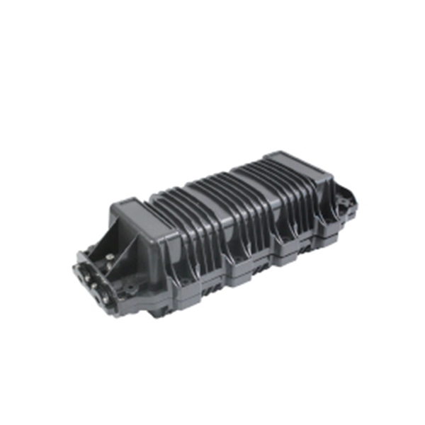
Product Features: Square protective box, suitable for skin cable and leather cable tight protection 6cm in length of skin heat shrink tube welding protection. A close connection between the leather cable and pigtail. Looking for specific info?. *In the era of high bandwidth, reliable fiber optic power equipment is particularly important. This handheld photometer can help check cable performance, calculate relative power loss, locate faults, and troubleshoot. *Measure the length of network cables, coaxial cables, and telephone cables. Able. Usually ships within 3 to 4 weeks Click here for details of availability. Able to test open, short, cross-connect, See more product details TABKER 4000667180167 3 x 2 x 1. Check each product page for other buying options. Price and other details may vary based on product size and color. Need help?. power across any given fiber. This document will serve as an overview of the major features and functions of the device and will ofer tips for trouble shooting com on issues in optical networks. If you are looking for a low cost device capable of saving and reporting take a look at the RP460 or. ments to the instrument's performance and functionality. The figures given in this manual ion of this manual to ensure the accuracy of its contents. However, should you have any questions or fi gistered users with a variety of information and services. Please allow us to serve you best by.
[PDF]

Diagram showing positive tip polarity on the left and negative tip polarity on the right. To read diagram: The center positive drawing on the left indicates that the center (also known as the tip) of the output plug is positive (+) and the barrel (ring) of the output plug is negative. The center positive drawing on the left indicates that the center (tip) of the output plug is positive (+) and the barrel of the output plug is negative (-). Symbol for a center-positive power supply. It is always good practice to test. The term positive terminal describes which of the two connection terminals on direct current (DC) equipment supplies or is meant to receive a positive electrical charge. DC power supplies always feature a positive to negative electron flow and always have a negative and positive terminal. Polarity. It is defined by the positive and negative terminals of a power source, such as a battery. Understanding polarity is essential because connecting a device to a power source with the correct. The rating plate of an Extra Low Voltage Power Supply (ELVPSU) shows various symbols and abbreviations. These represent critical information about the supply's ratings, class, polarity, and other safety details. The polarity symbol indicates if the centre (or tip) of the output plug is positive (+).
[PDF]

The core measurement procedure follows five steps: Turn on the meter and let it warm up. Most meters need a brief stabilization period before readings are reliable. Check your model's manual, but a minute or two is typical. Set the wavelength to match your light source. Fiber loss is the difference between the power when light is coupled from the transmitting end to the fiber and the power when the light reaches the receiving end. Generally speaking, when measuring the. An optical power meter measures the strength of light traveling through a fiber optic cable, giving you a reading in dBm (decibels relative to one milliwatt). The basic process is straightforward: turn the meter on, set it to the correct wavelength, clean your connectors, plug in, and read the. A power meter and light source are essential test tools that work in tandem to measure fiber optic cable loss and evaluate the quality of optical links. They provide the data necessary to quantify signal loss and pinpoint issues that could impact network performance. Here's how they work: A power. You measure optical power in dBm or insertion loss in dB. Verify light travels from transmitter to receiver. We'll give you the basic information you need and provide some printable references.
[PDF]
Distance relays, also known as impedance relay, differ in principle from other forms of protection in that their performance is not governed by the magnitude of the current or voltage in the protected circuit but rather on the ratio of these two quantities.OverviewIn, a protective relay is a device designed to trip a when a is detected. The first protective relays were electromagnetic devices, relying on coils operating on moving par. Electromechanical protective relays operate by either, or. Unlike switching type electromechanical with fixed and usually ill-defined operating voltage thresholds.
[PDF]

The modern electric power transmission, control, and distribution network demands precision, reliability, and advanced data analytics for each step in its operation. As a Relay Protection Engineer, your work in relay testing and commissioning is critical to ensuring system safety and continuity. In. The testing and verification of protection devices and arrangements introduces a number of issues. This happens because the main function of protection devices is related to operation under fault conditions so these devices cannot be tested under normal operating conditions. Protection relays are critical for detecting faults, initiating protective actions, and isolating faulty sections of the. Relay systems protect high-voltage equipment and transmission lines to ensure safe, stable systems. Although failure of a protective relay system may have severe local or regional impacts, most protective relay systems are not required to operate to prove they are in working order. Ensuring that. The strategies available to remove these risks are many, but all involve some kind of testing at site. Modern power systems are becoming increasingly complex, with growing demand, integration of renewable energy, and rising expectations for reliability and safety. In this environment, protection relays serve as the guardians of.
[PDF]
In, a protective relay is a device designed to trip a when a is detected. The first protective relays were electromagnetic devices, relying on coils operating on moving parts to provide detection of abnormal operating conditions such as over-current,, reverse flow, over-frequency, and under-frequency.
[PDF]

A protective relay is an intelligent electrical device designed to detect faults in power systems and initiate corrective actions such as tripping a circuit breaker. · Detection of the presence of a fault. · To close the trip circuit and operate the circuit breaker to isolate the faulty system from the healthier one. What is a protection relay? What is the purpose of protection. An electrically operated switch like a relay plays a key role in controlling an electrical circuit through an independent low-power signal, otherwise used where a number of circuits should be controlled through the single signal. Its main purpose is to safeguard electrical equipment like transformers, generators, and transmission lines from damage due to. A protection relay is a crucial component of electrical systems that safeguard infrastructure, employees, and equipment from electric problems and malfunctions. It functions as a watchdog by constantly surveying multiple system components including voltage, current, frequency, and phase angle. In other words, the prime function of protective relays is the timely and.
[PDF]

It can occur due to overloaded circuits, short circuits, or ground faults. Solution: Identify the Cause: Check if the breaker is tripping due to overloading. This often happens when too many devices are plugged into one circuit. Reducing the load on the circuit or redistributing. It's shutting off power because something on that circuit isn't safe. The tripping is a warning signal, not a malfunction. But what's causing it? And more importantly, does it need an expensive fix, or is this something simple? The good news: Most circuit breaker trips have straightforward. The main circuit breaker is designed to protect the electrical system in a building or home from overload and potential fire hazards. There are several reasons why a main circuit. A breaker box acts as the central hub that receives electricity from the utility company and distributes it to various circuits in your home. Homeowners will want to hire an electrician to determine the cause of the frequently tripping circuit breaker. When they start tripping, overheating, or making strange noises, it's more than just an inconvenience - it's your home's cry for help. In this guide, we'll walk through these. If you notice that your circuit breakers are often tripping, don't worry. It's a typical issue. Below, you'll find reasons why this occurs and tips to avoid it moving forward. Get a handle on your circuit breaker problems! Circuit breakers are protection devices for electrical circuits.
[PDF]
Electromechanical protective relays at a hydroelectric generating plant. The relays are in round glass cases. The rectangular devices are test connection blocks, used for testing and isolation of instrument transformer circuits.OverviewIn, a protective relay is a device designed to trip a when a is detected. The first protective relays were electromagnetic devices, relying on coils operating on moving par. Electromechanical protective relays operate by either, or. Unlike switching type electromechanical with fixed and usually ill-defined operating voltage thresholds. Electromechanical relays can be classified into several different types as follows: "Armature"-type relays have a pivoted lever supported on a hinge or knife-edge pivot, which carries a moving contact. These relays may.
[PDF]
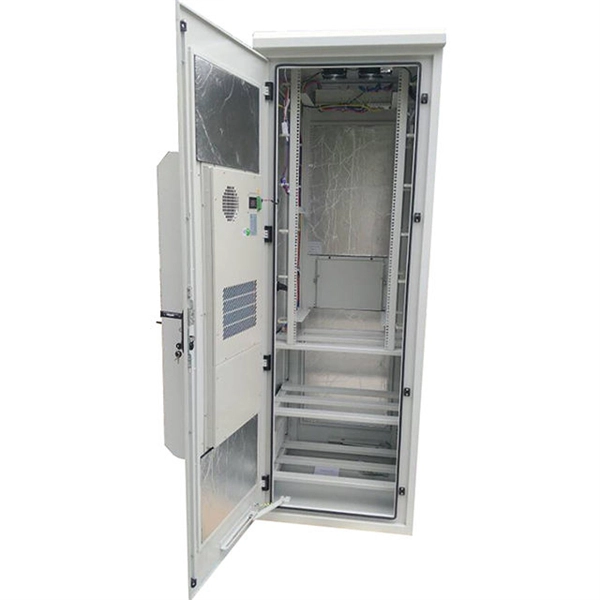
The distribution box is divided into power distribution box and lighting distribution box, which is the final equipment of the power distribution system. Both are strong electricity. The distribution box is a low-voltage power distribution device that assembles switchgear. A panelboard is a component of an electrical distribution system which divides an electrical power feed into branch circuits, while providing a protective circuit breaker or fuse for each circuit, in a common enclosure. A panelboard services to protect branch circuits from overloads and short. The distribution box is an electrical equipment with the characteristics of small size, easy installation, special technical performance, fixed position, unique configuration function, no site restrictions, widespread application, stable and reliable operation, high space utilization rate, small. A distribution box is according to the electrical wiring requirements of the switchgear, measuring instruments, protection appliances, and auxiliary equipment assembled in the enclosed or semi-enclosed metal cabinet or screen width, constituting a low-voltage power distribution device.
[PDF]
Fault Detection: Quickly identifies and isolates faults in the power system. Feeder Switching: Automatically switches power routes to maintain supply during faults. Outage Management: Reduces downtime by quickly restoring power. Voltage Control: Maintains stable voltage levels in the network. One key solution to this challenge is the adoption of distribution automation (DA) systems, which offer benefits including improved system reliability, enhanced crew safety and reduced outage durations. power distribution systems had adopted automated switching by the. This White Paper, “Smart Grid for Distribution Systems” addresses the benefits and challenges of implementing the many different Distribution Automation functions. Distribution systems have traditionally not involved much automation. Distribution equipment, once installed on feeders, was expected. Power Distribution Automation (PDA) involves the use of advanced technologies to enhance the efficiency, reliability, and safety of electrical power distribution networks. With automation.
[PDF]

In today's video, we'll be unboxing the 9-Port Power Supply Box and demonstrating how to connect the cables to provide power to CCTV cameras. A CCTV power supply box sends power to all your cameras from one place. It helps keep things neat and makes your system easier to manage. In this guide, you'll learn how to install it step by step, choose the right type, avoid common problems, and keep your system running safely. Power supply boxes for CCTV are typically used in multi-camera installations instead of using single power adapters for each camera. The process is almost exactly the same if you. Installers of surveillance systems may simply control the power to various CCTV cameras using a CCTV power supply box, also known as a power distribution box (usually at the location of the DVR). This enables a cleaner camera installation. Surge protection can be accomplished in two ways. The power supply box is specifically used to transfer power requirements for all cameras plugged in on the system, to work. Security cameras use RG59U coax siamese wire or CAT5e networking cable to transmit video. Whether you are installing a power box for a new or existing camera system, it is important to understand how to connect cameras to a CCTV Power Supply Box. DC current is polarized meaning it has two leads, a.
[PDF]
Electric power distribution systems are designed to serve their customers with reliable and high-quality power. The most common distribution system consists of simple radial circuits (feeders) that can be ove.
[PDF]

Electricity enters the box via the main breaker from the utility or generator. Power is passed to bus bars and adjusted to usable voltages (e. Breakers direct power to each circuit and trip during overloads. Neutral returns current; ground directs stray. A power distribution box (DB box) works by serving as a central electrical panel where electrical power is received and distributed from one input source to multiple output sources. This distribution box ensures the safe distribution of power throughout a building or area. Through its design and. A switchboard is a component of an electrical distribution system which divides an electrical power feed into branch circuits while providing a protective circuit breaker or fuse for each circuit in a common enclosure. Switchboards typically have a maximum voltage rating of 600 Vac/Vdc and a. A distribution box is a key part of electrical systems in buildings. Inside, you'll find parts like circuit breakers and fuses that protect the system from problems like overloads and short circuits. It ensures that electricity flows. Breakers are switches that turn off automatically when there's too much electricity or a short circuit. This helps prevent fires or damage. Without it, your devices and appliances could be in. Electrical switchboards are fundamental in controlling and distributing electricity in homes, offices, and industrial settings.
[PDF]

While optical power meters are the primary power measurement instrument, optical loss test sets (OLTSs) and optical time domain reflectometers (OTDRs) also measure power in testing loss. TIA standard test FOTP-95 covers the measurement of optical power. This measurement is the basis for loss measurements as well as the power from a source or presented at a receiver. Typically both transmitters and receivers have receptacles for fiber optic connectors, so measuring the. You need a power meter to measure power in a fiber optic system; most power meters come with a screw-on-adapter that matches the connector being tested and a little aid from the network electronics to turn on the transmitter. During the measurement of power, the meter must be set to the proper. Fluke Networks sets the standard in network testing with its advanced range of fiber optic power meters and fault locators, designed to ensure the highest precision in fiber optic meter readings and power evaluations. This is measured in decibels (dB). Splitters, fusion splices, connectors and. To use a power meter for fiber optic testing, always clean connectors first with lint-free wipes or click-to-clean tools. Select the correct wavelength and set your reference. Consistent procedures ensure accuracy.
[PDF]