An Optical Splitter, also known as a beam splitter, is a passive optical device that divides a single input optical signal into two or more output signals. Conversely, it can also combine multiple signals into one. Knowing the difference between a splitter and an optical coupler helps you build better networks. You make your network work better when you pick the right device for each job. You can connect many users to one port with 1:n or 2:n splitters. By dividing a single optical signal from a central Optical Line Terminal (OLT) into multiple outputs for Optical Network Terminals (ONTs) at users' homes, splitters eliminate the need for dedicated fibers to each residence—slashing infrastructure costs while scaling network reach. This guide. In a Passive Optical Network (PON), a single optical fiber carries massive amounts of data using light. Signal Input: The fiber splitter receives the optical signal from the upstream network node and enters the splitter through the input fiber. Signal Distribution: Inside the splitter, according to the design structure and different. Splitters are passive optical devices that divide or combine optical signals, and they come in various types, including power splitters, uneven splitters, and wavelength-division multiplexing (WDM) splitters. Each type serves specific applications, enabling efficient use of optical infrastructure.
[PDF]

A ladder type cable tray tee is a fitting used to create a branch in a cable tray system, allowing cables to be routed in three directions. Its "T" shape provides a secure and efficient way to split cables from a main tray into two separate paths, ensuring organized and flexible. A cable tray tee and tee cover are components used in cable management systems to support and protect electrical and data cables. Here's a brief explanation of each:. Rigid steel cable tray tee fitting with zero tangent, safety bottom, and full accessory support. ventilation to heat producing cable such as power communication and other with the same or different width of the cable run. All fittings are available in sizes and types corresponding to the straight cable tray sections. These fitting are including: elbow, horizontal cross, vertical inside. NOTE : Equal or un equal tees can be supplied. When ordering state widths W1xW2xW3.. Office: 147/22 Nguyen Sy Sach Street, 15 Ward, Tân Binh Dist, HCMC,VN. Is it possible to connect 2 cabletrays with a "branch piece (left picture)" instead of a "tee (right picture)". The tee has 3 connectors, the branch piece only has 1 connector. I would like to ajust the "Type properties -> Fittings -> Tee" with the branch family, but can't get it accomplished.
[PDF]
For systems with fewer than 32 channels, a core switch is generally unnecessary. Basically, the core switch is not required under 50 channels, the second layer switch plus router can be used, and the 100-channel or so will use the efficient routing function of the core switch. First of all, the 100-channel monitoring belongs to a medium-sized network. His network is under. Many engineers also say that I can manage 300 cameras without a core switch, and that's fine! With 10 years of experience as a security R&D engineer, I will tell you how to configure a core switch for cameras. What is a core switch? A network has three layers: access, aggregation, and core. Generally, large enterprise networks and Internet cafes need to buy core switches to achieve robust network scalability to protect the original resources. We will use. Core switches and edge switches are two essential components that play distinct roles in the functioning of a network.
[PDF]

Cable trays play a key part in keeping fire protection systems working. Here is what they do: They Make Safe Paths for Fire System Wires Cable trays are made from materials that resist fire. They can help stop fire from spreading. Recognize electrical cable tray misuse that can lead to electric shock and arc-flash/blast events and fires caused by overheating. The use and installation of cable trays is covered by legally enforceable OSHA regulations in 29 CFR 1910. 305(a)(3), or comparable standards promulgated by States. Scope: Firestopping for busway, cable trays, cables, and trunking passing through walls in enclosed electrical installations. Where cables pass through shafts, walls, slabs, or enter electrical panels or cabinets, openings shall be tightly sealed with firestopping materials in accordance with. Cable trays can be part of a planned cable management system to support, route, protect, and provide a pathway for cable systems. Power, low voltage control, data, or telecommunications wiring distribution systems can be used with cable trays. 1 This section applies to cable trays utilized to support and route low voltage cables (telecom, security, A/V). No fire alarm cables will be permitted to be installed in cable trays. If a fire starts, the tray protects the wires inside from flames and.
[PDF]

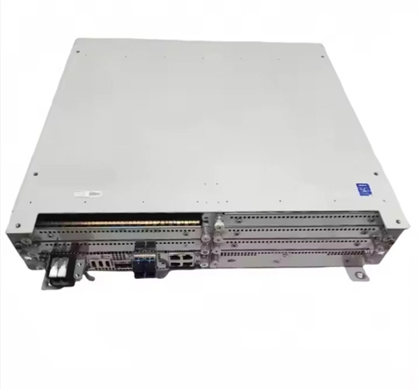
This article will introduce passive optical networks (PON), in which we will introduce everything about OLTs, ONTs, ONUs, and ODNs, including their operation principles and functions. PON (Passive Optical Network) refers to a fiber optic network built using a point-to-multipoint topology and fiber. Active Optical Networks (AON) and Passive Optical Networks (PON) make FTTH broadband connections possible. To date, most FTTH deployments in planning and deployment have used PON to save on fiber costs. PON has attracted much attention in recent years due to its low cost and high performance. There are no specific requirements for this document. This document is not restricted to specific software and hardware versions. The information in this document was created from the devices in a. OLT, ONU, ONT, and ODN are key components and acronyms used in Passive Optical Network (PON) architecture, which is a popular technology for delivering high-speed broadband services. This technology is widely used in fiber-to-the-home (FTTH) and fiber-to-the-premises (FTTP) deployments. In contrast to AON, multiple customers are connected to a single transceiver by means of. An Optical Distribution Network (ODN) serves as the bridge in a Passive Optical Network (PON), transmitting optical signals from the Optical Line Terminal (OLT) to the Optical Network Unit or Terminal (ONU/ONT), thus linking a service provider's core network to end-users (residential or business).
[PDF]
smart Malaysia has announced the launch of smartCare, an advanced aftersales service program designed to ensure the roadworthiness of all smart vehicles and provide proactive support to existing smart owners. This comprehensive program encompasses a range of services and features aimed at. Your smart cars comes with an exclusive 8 years or 200,000km for high-voltage battery warranty assurance to give you peace of mind. The high voltage battery 8 Years assurance period is up to 8 years from the date of registration and fully covered by smart included vehicle must be serviced at every. Enquiries on dealer locations and product availability Smart Solar Water Heater Sales & Service Malaysia Email: info@ecosmart. my Smartsolar hot water heater system come with digital temperature controller that you can read the temperature and control the backup heater automatically.
[PDF]
Learn about the two main types of fiber optic couplers: fused and planar. Fused couplers are cheap and work well. Pick the port setup that fits your needs. When it comes to proper fiber optic coupler selection, you will have to consider the effectiveness of the application in splitting and distributing optical signals without losing or interrupting the signal. If you choose poorly, the server signal will not be strong, there will be delays in. Fiber optic adapters, also known as couplers, play a crucial role in fiber optic networks by providing a connection point between two fiber optic connectors. They enable seamless and reliable optical signal transmission between different fiber optic cables, connectors, or devices. In this tutorial. This comprehensive guide explains what fiber optic adapters are, their common types, key selection criteria, cleaning best practices, frequently asked questions, and how customized connector solutions can benefit B2B projects in telecommunications, data centers, and industrial networks. What Is a. This small device connects or joins optical fibers together. It helps networks grow and change when needed. It provides an objective comparison to help you identify the best solutions for your networking needs. Unlike fiber splicing, which is permanent, connectors allow for easy connection and disconnection of cables, making them ideal for maintenance and flexibility in.
[PDF]

This video shows real on-site footage of electrical installation, demonstrating safe and standardized wiring methods used by professionals. more Learn how to wire a distribution box step by step! This video shows real on-site footage of. Material preparation: Prepare the required circuit breakers, wires, wiring ties and other materials, and ensure that they meet the design drawings and installation requirements. Location determination: Determine the installation position of the circuit breaker according to the position of the. Learn how to install a distribution box safely and correctly. Covers wiring, placement, standards, and expert tips for a compliant setup. A distribution box is the heart of any electrical system. It takes the incoming power and safely distributes it to different circuits throughout your building. And all the switching and protective devices are installed in the distribution box. Single Phase Distribution Box generally consists of Double Pole MCBs, Single Pole MCBs, and RCCBs. So here's what you need to know about wiring distribution panels, to make sure yours operates exactly as needed and as expected. Each circuit supplies a specific load, whether it's going to. Explosion-proof distribution boxes, vital terminal distribution equipment in power systems, play a crucial role in controlling and protecting industrial electricity in hazardous environments.
[PDF]

Use the SWD or JTAG interface to connect the ST-Link v2 to the STM32 microcontroller. Download and install STM32CubeIDE or another compatible IDE. Install the ST-Link USB driver (available on the STMicroelectronics. The ST-LINK/V2 is an in-circuit debugger/programmer for the STM8 and STM32 microcontrollers. The single wire interface module (SWIM) and the JTAG/serial wire debugging (SWD) interfaces facilitate communication with any STM8 or STM32 microcontroller operating on an application board. ATOLLIC, IAR and KEIL Integrated Development Environments for. How do you use SWD (Serial Wire Debug) for debugging STM32? - HackMD Using SWD (Serial Wire Debug) for debugging STM32 microcontrollers is a powerful way to monitor and control code execution, inspect registers, and analyze faults. Here's a step-by-step guide to set up and use SWD effectively: 1. In addition. This small guide will explain how to connect your debugger to your development board. There are two commonly used connectors which expose only the SWD (Serial Wire Debug) interface or the full JTAG interface. If you are using one of ST's official Nucleo or Discovery boards, you do not have to. To upload a program to a chip from Thomson Semiconductor you need an ST-Link programmer device to connect your PC. Thompson sells branded programmers, adaptors and cables. We'll use an inexpensive ST-LinkV2. They look like AVR programmers but you need to read the pinouts on the side.
[PDF]

Download XinZhiZao maintenance software to view the full CLEVO Notebook W230ST Schematic Diagram. The Schematic, Circuit Diagram PDF file for CLEVO Notebook W230ST Laptop Motherboard. Pages: 102, Format: PDF, File Size: 4. Page 5 This manual is intended for service personnel who have completed sufficient training to undertake the maintenance and inspection of personal computers. It is organized to allow you to look up basic information for servicing and/or upgrading components of the W230ST se- ries notebook PC. Page. These drivers or Manuals are customized for CLEVO's Notebook PCs only. We would not advise using them with other vendors' products. If you have any problem about file linking error, please mail to marketing@clevo. tw If can't download a file with IE11, please try with Firefox or Chrome to. My Clevo W230ST 6-7P-W2304-003 motherboard is faulty so I'm searching for the repair & services guide with electronics schematics to see how to fix it. I'd like to measure the different chips voltage so if someone could help me find and download the Clevo W230ST 6-7P-W2304-003 service manual it. We have 29 Asus WSeries W230ST Motherboards / System and laptop parts in stock and available for immediate shipment. Asus W Series W230ST Motherboards / System Replacement Laptop Parts. Battery, Keyboard, Fan. Notebook Clevo W230ST - Service manuals and Schematics, Disassembly / Assembly.
[PDF]
5″ hard drive with a storage capacity of 80GB and featuring a IDE interface. ST380011A Seagate Barracuda 80GB 7200RPM ATA/EIDE 2MB Cache 3. 5-inch Low Profile (1. All information about the Seagate ST380011A hard disk drive: technical parameters, failure. 8-Mbyte buffer on: ST3200822A, ST3160023A, ST3120026A, and ST380013A High instantaneous (burst) data transfer rates (up to 100 Mbytes per second) using Ultra DMA mode 5. Giant magnetoresistive (GMR) recording heads and EPRML technology, which provide the drives with increased areal density. Manuals and User Guides for Seagate Barracuda 7200. 7 ST380011A Drive manuals available for free PDF download: Product Manual, Installation Manual Figure 3. Breather Filter Hole Location Figure 4. Ultra ATA. 1. 7 Plus • ST3160023A • ST3120026A • ST380013A Barracuda 7200. 7 • ST3160021A • ST3120022A • ST380011A • ST360014A • ST340014A These. HITACHI HDS721032DLE630 (320 GB S-ATA Gen3) SAMSUNG HS10XJC (100 GB IDE) SEAGATE ST9250612NS (250 GB S-ATA Gen3) Device manufacturers may change any parameters without prior notice. There is no warranty that the information listed here is complete and accurate. If you encounter any improper value. Our goal is to provide you with a quick access to the content of the user manual for Seagate Barracuda ST380011A. If looking through the.
[PDF]
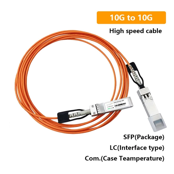
Connect the fiber optic cable: Attach the fiber optic cable's connector to the transceiver module on the switch. Make sure the connector type (e., SC, LC) matches the transceiver module. Fiber optic cabling is increasingly used to connect network switches and other datacom equipment, especially in long-distance and mission-critical applications. Fiber provides: Increased internet signal bandwidth. Most modern fiber-enabled network switches require an SFP transceiver module. This document describes how to troubleshoot fiber optic interfaces by addressing some of the fiber optic module and cabling specifications. There are no specific requirements for this document. The information in this document is based on all Catalyst 9000 Series switches. This includes Doppler. Connecting a switch to a fiber optic network involves several steps and requires specific equipment to ensure a successful and efficient connection. If you're looking to learn how to configure fiber optics on a Cisco switch, it's important to first configure the switch settings so it's ready for fiber optics. Fiber optic switches utilize. Other than entry level network switches, most of today's network switches include one or more GiBC (Gigabit Converter) or SFP (Small Form-factor Pluggable) slots. SFP modules insert into these slots and and require two strands of fiber, typically duplex Using multi mode fiber (for runs under 1000.
[PDF]
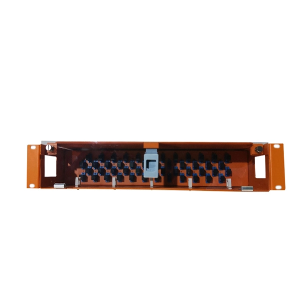
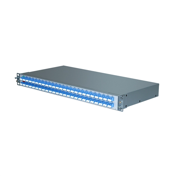
When deploying fiber optics in the field, telecommunications companies need ways to safely and efficiently store and terminate cables. As many technicians know, having the right fiber optic patch and splic.
[PDF]
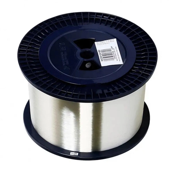
Single mode and multimode fiber optic cables are two different types of fiber optic cable aimed at different use cases. Single mode cables are typically made with a single strand of glass at their core, leading to a n.
[PDF]

Voltage droop is the temporary reduction in the output voltage of a power source that occurs when the system suddenly draws a significant amount of electrical current. This drop is a fundamental consequence of electricity moving through materials that are not perfect conductors. The sudden increase. Voltage anomalies in telecom power systems disrupt network stability, often causing unexpected outages and costly downtime. Operators face significant challenges when faults go undetected, risking both equipment and service reliability. Power-related failures account for nearly one-third of telecom. Voltage stability in power systems can be impacted by various disturbances; including faults, load changes, equipment failures, and weather events. Instability can cause severe issues like loss of load, cascading outages, and the loss of synchronism in generators. Every conductor, regardless of material or size, possesses some amount of resistance that impedes current flow and converts electrical energy. Voltage dropping is a power quality condition where voltage at equipment terminals falls below expected operating levels during load conditions, causing instability, fluctuating performance, and observable changes in electrical system behavior. It is dynamic, load-driven, and often intermittent. Voltage drops and power losses in power lines are common and normal phenomena. They are associated with the flow of current through the different network components.
[PDF]