The SFP transceiver is not standardized by any official standards body, but rather is specified by a (MSA) among competing manufacturers. The SFP was designed after the interface, and allows greater port density (number of transceivers per given area) than the GBIC, which is why SFP is also known as mini-GBIC. However, as a practical matter, some networking equipment manufacturers engage in pr.
[PDF]
Silicon is to with wavelengths above about 1.1 micrometres. Silicon also has a very high, of about 3.5. The tight optical confinement provided by this high index allows for microscopic, which may have cross-sectional dimensions of only a few hundred. Single mode propagation can be achieved, thus (like ) eliminating the problem of.
[PDF]
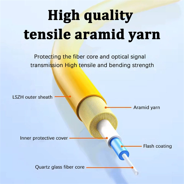
Silicon photonics (SiPh) is a technology that combines electronics and photonics, miniaturizing optical circuits into a small chip and using optical waveguides to transmit light signals within the chip. The increasing bandwidth demands brought on by AI are now. Silicon photonics is the study and application of photonic systems which use silicon as an optical medium. The silicon is usually patterned with sub-micrometre precision, into microphotonic components. These operate in the infrared, most commonly at the 1. This technology has gained significant traction, especially with the advent of 800G and 1. Unlike traditional chips that rely on electrical signals for data transmission, silicon photonics uses photons as the medium, transmitting data through optical waveguides. These are the pluggable optical modules that convert electrical signals to optical signals and back again. They are inserted into the network device and terminate the fiber optic cabling that runs throughout the network's physical infrastructure. Unlike the ASIC and CPU chips that act as the brains. In response to this challenge, experts have begun exploring new approaches such as integrating different functional ICs into a single chip and adopting 3D stacking packaging technology.
[PDF]

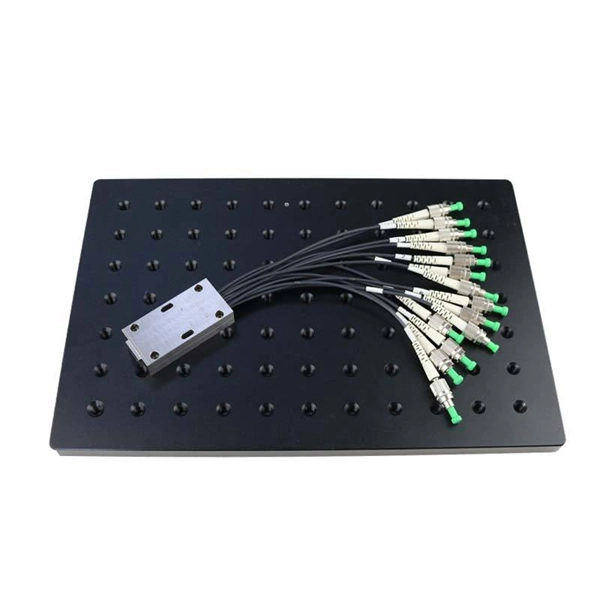
An Optical Splitter, also known as a beam splitter, is a passive optical device that divides a single input optical signal into two or more output signals. Conversely, it can also combine multiple signals into one. Knowing the difference between a splitter and an optical coupler helps you build better networks. You make your network work better when you pick the right device for each job. You can connect many users to one port with 1:n or 2:n splitters. By dividing a single optical signal from a central Optical Line Terminal (OLT) into multiple outputs for Optical Network Terminals (ONTs) at users' homes, splitters eliminate the need for dedicated fibers to each residence—slashing infrastructure costs while scaling network reach. This guide. In a Passive Optical Network (PON), a single optical fiber carries massive amounts of data using light. Signal Input: The fiber splitter receives the optical signal from the upstream network node and enters the splitter through the input fiber. Signal Distribution: Inside the splitter, according to the design structure and different. Splitters are passive optical devices that divide or combine optical signals, and they come in various types, including power splitters, uneven splitters, and wavelength-division multiplexing (WDM) splitters. Each type serves specific applications, enabling efficient use of optical infrastructure.
[PDF]

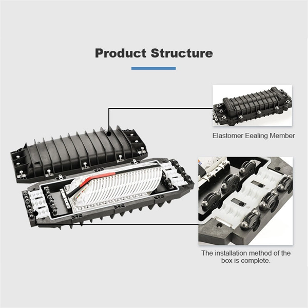
Cable Trays* — Max two 24 in. (610 mm) wide by max 6 in. (151 mm) deep open-ladder cable tray with channel-shaped side rails formed of 0. 54 mm) thick aluminum or min 0. In practice, cable tray dimensions are a system of interrelated measurements —width, depth, length, and material thickness—that directly affect cable fill compliance, heat dissipation, structural loading, and long-term expandability. From an engineering standpoint, cable tray dimensions are not. Perforated Cable Tray System expertly constructed from high-grade stainless steel, offering exceptional durability and resistance to corrosion. With side height 100mm. A properly designed and installed cable tray system will provide. Studs — Wall framing to consist of wood studs or channel shaped steel studs. Wood studs to consist of nom 2 by 4 in. Additional studs shall be used to completely frame. Best Size: Here, deep trays (75mm to 150mm) are used since power cables are typically thick and heavy. Data cables, such as your Wi-Fi or computer ones, are extremely sensitive. They do not get hot; however, they do not like to hang or sag. In case a data cable folds in an excessive manner, the. ect the minimum bend ra-dius for cables as they exit the bottom of the cable tray. A rung spacing of 6 to 9 inches (150 to 230 mm) is preferable when the cable tray cont d for instrumentation and control applications that require additional protec eferred to support and protect numerous small.
[PDF]
The Planar Optical Waveguide Chip Market, valued at USD 1. 97B in 2026, is projected to reach USD 3. In this report, we will assess the current U. tariff framework alongside international policy adaptations, analyzing their. The global market for Planar Optical Waveguide Chip was valued at US$ million in the year 2024 and is projected to reach a revised size of US$ million by 2031, growing at a CAGR of %during the forecast period. Planar optical waveguide chip is a micro-optical device based on silicon-based. Planar Optical Waveguide Chip by Application (Optical Communication, Data Center, AI, Other), by Types (1xN, 2xN), by North America (United States, Canada, Mexico), by South America (Brazil, Argentina, Rest of South America), by Europe (United Kingdom, Germany, France, Italy, Spain, Russia. The Planar Optical Waveguide Chip Market was valued at USD 1. 97 billion in 2026, with a CAGR of 11. The evolution of planar optical waveguide chips demands a concise introduction that frames technology. This definitive report equips CEOs, marketing directors, and investors with a 360° view of the global Planar Optical Waveguide Chip market, seamlessly integrating production capacity and sales performance across the value chain. 2 USD Billion by 2035.
[PDF]