This calculator determines the maximum number of cables that can be safely housed within a cable tray based on its dimensions and the cross-sectional area of the cables. Proper tray and ladder sizing ensures safe, efficient, and maintainable electrical installations in all engineering applications. IEC 61537 and IEC 60364 require evaluating tray dimensions based on cable quantity, type, and layout configuration. Below are industry-standard tray and ladder. A Cable Tray Capacity Calculator is an essential tool for electrical engineers, contractors, and project managers involved in the installation and management of electrical cables. Calculate Cable Cable Calculate the cross-sectional area of a single cable, then multiply by the total number of cables. For mixed cables, sum the areas of all individual cables. Plan cable trays with fill, weight, spacing, and growth checks. Compare standard sizes quickly now. Export clear results for safer electrical layouts and upgrades. The following formula is used to calculate the cable tray capacity: Variables: To calculate the cable tray capacity, multiply the width and height of the cable. This is best exhibited by cable tray width calculations for three different examples of single conductor cables in ladder or ventilated trough cable tray that are permitted by NEC Article 318. The examples are based on installations that contain 12 - 500 kcmil cables (four - three phase - 480 volt.
[PDF]
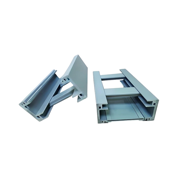
You can buy a manufactured 90 degree bend or make one on a cable tray bending machine but in this video I show you how to make one using a metal bar. Students trading aid on how best to put an internal 90 degrees bend in steel cable tray. more. The bends, tees, crosses, risers and reducers of wire mesh cable tray can be easily and quickly made live at the project by using a bolt cutter. Since the jaws of the bolt cutter drags a layer of zinc across the cut end and forms a protective layer. When a wire cable tray is cut, the fact that a. Choose a cable tray fitting with a radius equal to or greater than your calculated minimum. Common standards are 300, 450, 600, and 900 mm. How to calculate cable tray bends? Calculate the minimum required bend radius by multiplying the cable's outside diameter by its bending factor (e., 10x for. Use this guide to learn the most effective installation practices when installing Cablofil tray. Each example of bends and tee's clearly illustrate proper tray cutting combined with recommended usage of Cablofil accessories. This involves a few essential steps to ensure a successful bending process. The first step in preparing the. ns and Cross Joints. These arrangements can be created by using our standard cable tray sections and removing specific pieces as directed using the Cutter tool (WR-TRAYCTR65), and then bending and securing the tray pieces together using Couplers (WR-CPLKK34), Corner Strength Bars (WR-CNRSBAR-EZ).
[PDF]
Dense wavelength-division multiplexing (DWDM) refers originally to optical signals multiplexed within the 1550 nm band so as to leverage the capabilities (and cost) of EDFAs, which are effective for wavelengths between approximately 1525–1565 nm (), or 1570–1610 nm (). EDFAs were originally developed to replace optical-electrical-optical (OEO), which they have made pra.
[PDF]
The original unstructured record data for the defect of the relay protection devices (RPDs) may contain problems influencing the data mining, and it is lack of quantitative evaluation. So the purpose of this.
[PDF]

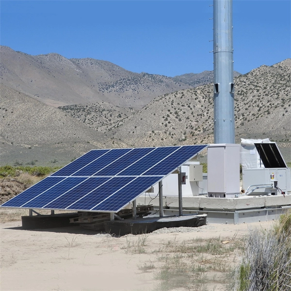
In modern FTTH architectures, the ODN is the physical fiber layer that distributes optical signals from the central office to end users. Operators consider ODN design as one of the most important factors affecting: Network coverage Optical loss performance Deployment cost. This passive layer is known as the Optical Distribution Network (ODN). Its role is to provide an optical transmission channel between the OLT and the ONU. The ODN network design is a physical facility that connects the communication room and user equipment, and is a key component. Short summary: The Optical Distribution Network (ODN) is the passive infrastructure linking the central office to the subscriber in FTTH. This guide delves into essential ODN components like splitters, distribution boxes, and ODFs, showcasing how Hainan ZTO Cable Co. It's the silent, robust highway that delivers blazing-fast Fiber-to-the-Home (FTTH) and 5G services. The maximum permissible optical power attenuation between OLT optical ports to ONT input is 28dB, which is by utilizing the so-called Class B optical network. At the heart of every Fiber-to-the-Home (FTTH) deployment lies the Optical Distribution Network (ODN) — a meticulously engineered passive infrastructure that enables operators to deliver massive bandwidth, low latency, and reliable service to millions of users. The ODN connects the Optical Line.
[PDF]

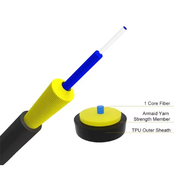
This guide aims to provide a concise understanding of multimode fiber optic cable and its applications. We will explore its characteristics, advantages, specifications, and real-world uses. Multimode fiber (MMF) is an optical fiber designed to carry multiple light propagation paths—or modes—simultaneously. This is made possible by its relatively large core diameter, typically 50 or 62. 5 microns, compared to the ~9-micron core in single-mode fiber. The wider core accepts light from. Multimode fiber optic cables are essential in modern data communication systems since they can transmit data efficiently and at high speeds over short and medium distances. We will explore its. They consist of a transmitter on one end of a fiber and a receiver on the other end. Most systems operate by transmitting in one direction on one fiber and in the reverse direction on another fiber for full duplex operation. Most systems use a "transceiver" which includes both transmission and. Multi-mode optical fiber is a type of optical fiber mostly used for communication over short distances, such as within a building or on a campus. Multi-mode links can be used for data rates up to 800 Gbit/s.
[PDF]

This guide will walk you through the process of checking photo sensors using a multimeter, covering various types of photo sensors, the necessary tools and safety precautions, and the specific measurement techniques involved. Knowing how to effectively use a multimeter to test photo sensors can save you time, money, and frustration when dealing with malfunctioning devices. more What is a Voltage Divider? | What is a Voltage. Before replacing the sensor or fixture, it's efficient testing it first, With a few tools and a step-by-step process you can find whether your outdoor lighting control system is working as intended or if the problem lies elsewhere. In this complete guide from Lead-Top, a global leader in photocell. In this blog post, we explain step-by-step how to troubleshoot a sensor with a digital multimeter (DMM). Here are the steps: Troubleshooting a sensor measurement failure requires mechanical tools to uncover the protective shields or components so you can reach the sensor in question. Always follow the manufacturer's instructions for the sensor and multimeter. Ensure the sensor is properly connected to the multimeter and. A multimeter is an indispensable diagnostic tool for anyone working with electronics, electrical systems, or indeed, sensors. It's a versatile device capable of measuring voltage, current, and resistance, providing crucial insights into the health and functionality of electrical circuits and.
[PDF]
To set up your router for fiber internet quickly, connect the router to your fiber modem, access the router's settings via a web browser, and input the provided ISP credentials. Make sure to update the firmware, configure Wi-Fi security, and customize your network name for. Q: How do I install my broadband modem and set up my Internet connection? Installing your broadband modem and setting up your Internet connection involves several steps. First, you need to physically connect your modem to your computer using an Ethernet cable or wirelessly through a router. Next. This wikiHow guide will walk you through setting up a Wi-Fi connection in Windows XP and connecting to the internet. We'll also cover the risks so you know what you're getting into. Check for or install a wireless adapter. Enable Wireless Zero Configuration. Right-click the network icon. Why Use Fiber Optic Internet? Before diving into the setup, let's quickly. Setting up a home network on Windows XP can seem like a daunting task for beginners, but with the right guidance, it becomes a straightforward and rewarding endeavor. This beginner's guide is designed to walk you through the easy steps necessary to establish a functional network within your own. This article provides a detailed guide for establishing internet connectivity in Windows XP via dial-up modem, Ethernet, and Wireless connections, including troubleshooting common issues.
[PDF]
A grid networks consist of an interconnected grid of circuits, energized from several primary feeders through distribution transformers at multiple locations. Grid networks are typically featured in.
[PDF]

Key finding: This paper develops analytical models and design procedures of ultra-wideband Wilkinson power dividers using linearly tapered transmission lines (TTLs) which provide size reduction and broadband performance. Read more. Power dividers are the passive electronic equipment used for splitting the power. They are now being employed in a variety of communications applications such as telephonic, antennas configurations, mobile connectivity, internet technology, & optics, etc. They come up with very low loss, operate at. RF and microwave power splitters and dividers create two copies of the same signal, while ideally preventing crosstalk between the outputs. Doing this with minimal loss while maintaining signal integrity is a challenge. In this article we explain how power splitters work and what the tradeoffs are. The rise of wireless connectivity requirements for applications such as Internet of Things (IoT), cellular, and automotive electronics is resulting in systems that are increasingly using RF signals, components, and subsystems. Often, designers need to direct these signals to more than a single. A power divider is a passive electronic device used in radio frequency (RF) and microwave applications to split an input signal into multiple output signals with equal or specified power levels, while maintaining impedance matching to minimize signal reflection and loss. How can power dividers.
[PDF]
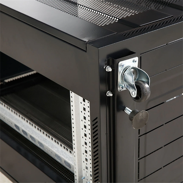
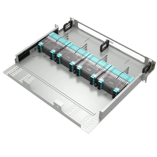
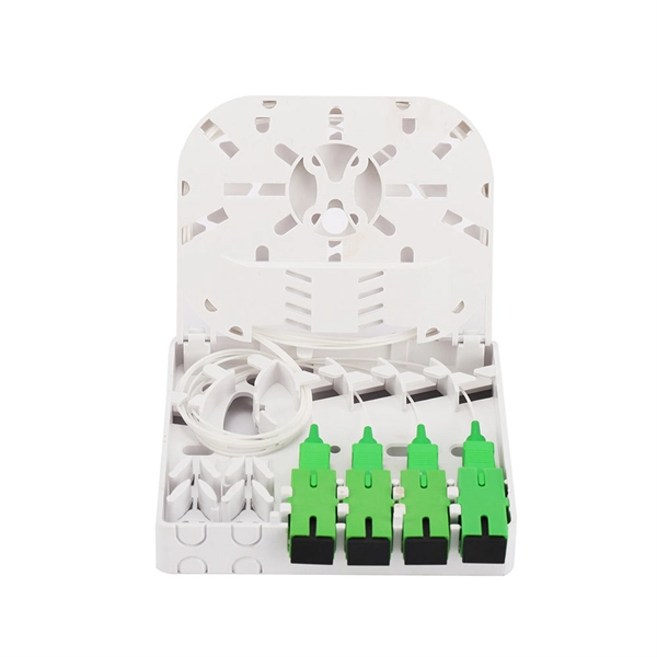
The XL type low-voltage power distribution cabinet uses domestically designed new components. The enclosure is made of bent steel plates, featuring a compact structure, easy maintenance, and flexible circuit scheme combinations. The 19-inch rack-mounted end box is a passive component for terminal distribution of trunk cables in fiber-optic communication systems, with tools for easy connection and distribution of fiber optic circuits. Sopto offers 19 Inch Rack Drawer Distribution box (Fiber Patch Panel) and 19 Inch Rack. 2 Core Fiber Optic Distribution Indoor Box (wall mount box type) © 2024 E-Talk Maldives. Nuomak is proud to announce a new cooperation with a client in the Maldives, for whom we have manufactured PS cabinets, MCCBs, and transparent waterproof electrical distribution boxes. These products are specially designed to meet the challenges of high humidity, salt spray, and harsh coastal. Need assistance? Let us help you with your questions and queries. Send a message to Viber: 7317894 Promotions, new products and sales. Directly to your inbox. Besides air circuit breakers and fuses for circuit protection, the. The electrical enclosure is made of wear-resistant and rust-resistant stainless steel, which can be widely used in indoor and outdoor applications, such as power, construction and other industries; allowing your equipment to be well protected in harsh environments. · Easy installation and easy.
[PDF]
Key cost drivers include panel amperage, indoor vs outdoor location, wiring length, and whether a full panel upgrade or rerouting is needed. Your practical guide to smart power solutions for modern buildings Ever walked into a room and flipped a switch without thinking about what makes the lights come on? That's the magic of a well-designed electrical system. Whether you are a seasoned procurement officer or a first-time project manager, understanding the distribution box market is about more. The global market for Distribution Boxes was estimated to be worth US$ million in 2023 and is forecast to a readjusted size of US$ million by 2030 with a CAGR of % during the forecast period 2024-2030. North American market for Distribution Boxes was valued at $ million in 2023 and will reach $. Homeowners typically spend several hundred to several thousand dollars for distribution box work in septic systems, depending on system size, material, and installation complexity. The main cost drivers are the number of boxes, trenching, backfill, and permit requirements. The article outlines cost ranges, per-unit pricing, and practical. In this guide, we will explore the key factors that impact pricing in the industry and help you make informed decisions when selecting a warehousing and distribution service provider that meets your needs and budget. As shown in the chart above, warehousing & distribution services on Clutch are.
[PDF]

An optical module's actual transmit power measured by an optical power meter is lower than the nominal transmit power of the power module. The possible causes are: Bores of the optical module are contaminated. Stable optical power is the foundation of every high-capacity optical transport system. Even minor deviations—whether too high, too low, or unstable—can impact signal integrity, trigger service alarms, or interrupt traffic on DWDM, OTN, or long-haul optical line systems. This is the domain of Cell-to-Module (CTM) power loss, a series of. This paper reviews methods for reducing different optical and electrical loss mechanisms in PV modules and for increasing the optical gains in order to achieve higher CTM ratios. Various solutions for optimizing PV modules by means of simulations and experimental prototypes are recommended. Have you ever experienced an unexpected network outage due to the failure of an SFP/SFP+ optical transceiver? Network outages can bring your ability to communicate and work to a halt, and your IT team will likely be frantically looking for a solution. It is important to understand how to. This article provides an in-depth analysis of two key performance indicators of optical modules: transmitter power and receiver sensitivity. Transmitter power characterizes the average optical power output from the laser under rated conditions, while receiver sensitivity indicates the minimum.
[PDF]
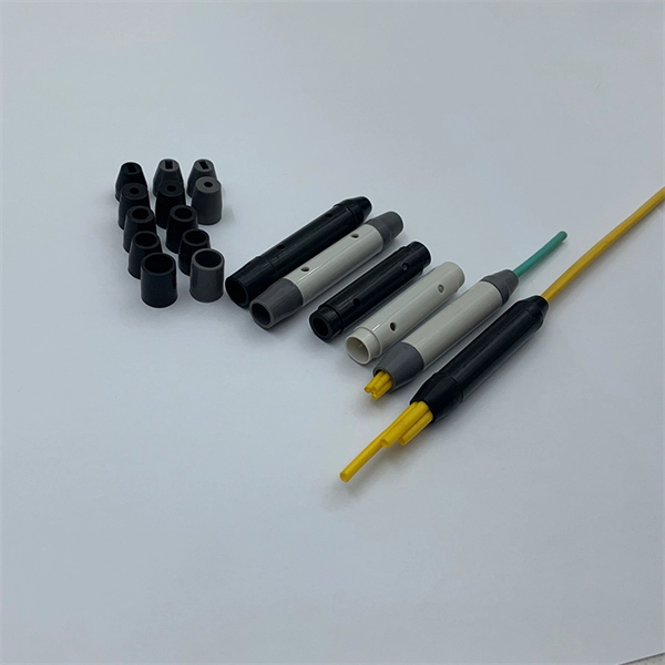
There are several diagnostic methods to help troubleshoot fiber optic connectors, and the diagnostic method is to cross-section the fiber optic connector. This technology allows us to actually look inside the fiber optic connector to see defects and pinpoint the cause of. Fiber design and transmission technology have collaboratively evolved to increase bandwidth. Dig-ups dominate! Cablers have very little influence on the majority of causes of cable field failures. While a small percentage, we can examine the “intrinsic” cable failures and what is done to prevent. Connector failure is most frequently the result of a dirty or damaged end-face. Fiber-optic connector: SC type In the connector, the element that holds the fiber and provides the alignment positioning is the ferrule. The. In August of 1999, Boeing Corporation (Boeing) engineers being used on International Space Station flight a defect in the glass fiber (see Figure 1, “Rocket and NASA engineers and managers, Boeing created and reliability of the cable installed in the U. Fiber coupling can be accomplished by fusion splicing.
[PDF]
This comprehensive guide breaks down the internal structure, core components (TOSA, ROSA, lasers), and operational mechanisms of SFP optical modules, enriched with technical insights and real-world applications. As core components for photoelectric conversion in optical communication systems, data center interconnection, and long-haul transmission, optical modules rely on TOSA and ROSA to realize high-speed signal conversion. Now, ETU-LINK will introduce to you the components of the optical module— TOSA. TOSA, ROSA, and BOSA are critical components in optical transceivers. These modules play a vital role in transmitting and receiving optical signals. TOSA ( Transmitter Optical Sub-Assembly), converts electrical signals into optical signals for transmission. OSAs generally fall into three main categories: TOSA, ROSA, and BOSA. • TOSA TOSA: Transmitting Optical Sub-Assembly. First of all, the two most important parts of the optical module are the Transmitter Optical Subassembly (TOSA) and the Receiver Optical Subassembly (ROSA).
[PDF]