5 inch CETC Optic fiber OTDR AV6418,Fiber optic test tester,1310/1550nm,45/43dB large dynamic range,built in Optic power meter and VFL Description: AV6418 OTDR mainly used to measure the physical characteristics of optical fiber under test,such as the length,the transmission loss. 6. 5-inch display offers an event blind zone of 1 m and operates with locater This product is already in your quote request list. Measuring Measuring loss (dB) in the range between 800nm – 1700nm. Power AC/DC adapter; Input:100V~240V, 50/60Hz. Polarization extinction ratio (PER) is a measure of the degree to which light is confined in a principal linear polarization mode. It is defined as the ratio of the power in the principal polarization mode to the power in the orthogonal polarization mode after propagation through a device or. The ERM2xx Extinction Ratio Meters measure the polarization extinction ratio (PER) and the polarization angle of polarization-maintaining (PM) fibers. It features unmatched low cost, all wavelength options, a large dynamic range, and high resolution. The design adds a rotary polarizer to an optical power meter.
[PDF]

Fiber Optic Polarization Extinction Ratio Benchtop Meter for wavelengths from 850 nm to 1650 nm. ER = 30dB for wavelengths from 850 nm to 1290 nm and ER=35dB for wavelengths longer than 1290 nm. Receptacle is not included. Input power is up to 1 mW. Description Handheld Type; 400 to 2400 nm; Extinction Ratio Range 30, 35, 40 dB; Extinction Ratio Accuracy ±1 dB; Angular Accuracy ±0. 5°; Adapter Type FC/PC, ST, E2000. The PEM-400 is an instrument developed for high-volume testing of the polarization extinction ratio (PER) of polarization maintaining (PM) components such as fiber array units (FAU) and external laser small form-factor pluggables (ELSFP). A polarizer is rotated in front of a high-speed power meter. The ERM-202 is a rotating-polarizer polarization extinction ratio meter. It is available in single or dual channel versions. The ERM-202 combines low noise circuitry with a high resolution stepper motor to achieve a PER dynamic range of 50 dB and angle resolution of 0. It is widely used in. It features unmatched low cost, all wavelength options, a large dynamic range, and high resolution. The design adds a rotary polarizer to an optical power meter.
[PDF]
Find top-rated polarization extinction ratio meters with >40dB performance, real-time measurement, and USB output. Compare verified suppliers, pricing, and specs. Click to discover reliable options for lab and field use. The ERM2xx Extinction Ratio Meters measure the polarization extinction ratio (PER) and the polarization angle of polarization-maintaining (PM) fibers. These easy-to-use benchtop devices are useful in alignment applications such as connectorization of PM fibers or pigtailing of laser diodes with PM. This is the CUBE-ER100 and CUBE-PM100 Duo for automated high dynamic PER measurement (>46dB) CUBE-PM100 converts the polarization of the input broadband light to linear polarization through a higher PER (>50dB) polarizer. It then couples the linearly polarized light into the PM fiber under test. A polarizer is rotated in front of a high-speed power meter. The ERM-202 is a rotating-polarizer polarization extinction ratio meter. It is available in single or dual channel versions. The ERM-202 combines low noise circuitry with a high resolution stepper motor to achieve a PER dynamic range of 50 dB and angle resolution of 0. It simultaneously. OZ Optics Online. Please check your network connection and try again.
[PDF]

The socket accepts laser diodes with wire leads 24 to 26 gauge, 0. The maximum recommended current is 3 Amps. Specifications: Outside dimensions: 0. Thorlabs offers a versatile range of accessories for convenient integration of laser diodes into functional systems. These laser diode sockets are ideal for OEM-type implementations and are compatible with our selection of Ø3. 6 mm, Ø9 mm, and TO-5 laser diode packages. All of these sockets. Wide Range of Standard Products and Flexible Customization We offer a variety of standard products with different pitches, pin counts, and pin arrangements, helping to shorten lead times. Compatible with TO-18, TO-46, TO-52, TO-72, and more (please refer to the lineup at the bottom of the page for. Pricing (USD) Filter the results in the table by unit price based on your quantity. A tariff of 8% may be applied if shipping to the United States. A. Compact miniature socket size for maximum board density Accomodates most any TO package format with pin circle options of. The S8060 and S8060-4 sockets have a polarization dot on the top of. 4-Pins Laser Diode Test Socket High Precision Diode Test Stand 1. The inner hole of the pin is a through hole, and the length of the laser diode to be tested can be universal. The pins are made of gold-plated copper tubes, low resistance, not easy to oxidize, long service life.
[PDF]

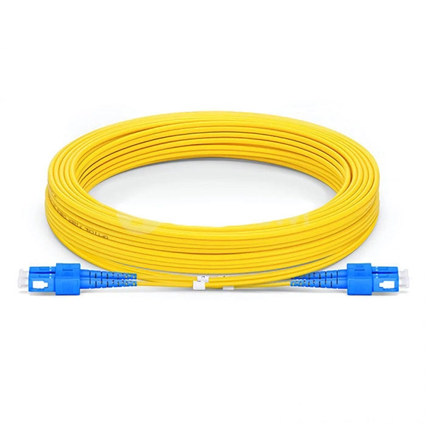
Regularly testing fiber optic cables helps minimize network downtime, lengthens the network's longevity, reduces maintenance requirements, and helps support network reconfiguration and upgrades. Fiber optic testing ensures the performance and reliability of fiber optic networks. Key tests include: Effective fiber testing utilizes advanced tools such as Optical. Fiber optic testing for continuity is crucial in ensuring that light transmits through fiber optic cables without interruptions, safeguarding seamless data transmission. This guide talks about the primary methods and tools for effective continuity testing in fiber optic cable networks. Insertion loss testing confirms whether the cable meets design loss budgets. OTDR testing identifies events along the fiber length, including: OTDR is essential for long-distance FTTH feeder and distribution cables. After the cables are installed and terminated, it's time for testing. For every fiber optic cable plant, you will need to test for continuity, end-to-end loss and then troubleshoot the problems. If it's a long outside plant cable with intermediate splices, you will probably want to verify the. We'll explain why it's vital to test fiber optic cables, the three most popular methods, and when you should use them. Why Testing Fiber Optic Cables Matters? Regular testing of fiber optic cables is not just a preventive measure; it's an.
[PDF]

Fiber optic connector pull test demonstration with real-time insertion loss monitoring. We use an optical loss tester to track signal stability every second while controlled tension is applied to the fiber. more. Fiber optic cable is surprisingly strong, durable and pliable; however, several best practices should be followed to ensure a successful cable installation. The below article explores the best practices and tools commonly used to pull fiber optic cable. The Future Ready Solutions Tools & Test. NEOFIBO TFTM-100N Vertical Fiber Optics Cable Tension Testing Machine The Cable Tensile Testing Machine is a precision mechanical measuring instrument designed to evaluate the tensile strength and elongation properties of various cables, wires, and fiber optic assemblies. Most fiber damage does not come from normal operation after the system is live. It happens during installation, when excessive pulling force, tight bends. Fiber optic connectors are designed to be connected and disconnected many times without affecting the optical performance of the fiber circuit. Optimal performance can be achieved by following the correct process for termination of the fiber circuit—a task which requires the use of a wide range of. The Fluke Networks JR-LEV-1 JackRapid Punch Down Tool is a cable termination tool that is designed to give technicians maximal efficiency in cable maintenance.
[PDF]

The fastest way to test a fluorescent tube is with a multimeter set to continuity mode. Each end of the tube has two pins connected by a thin filament inside the glass. If either filament is broken, the tube is dead. The whole test takes about 30 seconds per tube once you know what. This is a complete guide for testing a fluorescent light bulb with a multimeter. You don't have to be an expert in electrical work. This process measures electrical resistance to determine if the tube has suffered an internal failure before replacing the bulb or investigating the ballast. This guide provides a comprehensive understanding of the process, equipping you with the knowledge and. To test a fluorescent light bulb, observe any of the following: flickering light, low brightness, buzzing sound, delayed start, and fading color and light variation. Turn off the power to the circuit that powers the fixture and keep the leads steady to ensure accurate readings. Multimeters provide. How to Test Light Bulbs & Fluorescent Tubes with a Multimeter (Continuity Check) Is your lamp or fixture failing to light up? Before you buy a new bulb, you need to confirm if the bulb or tube itself is the problem! A simple continuity check using a multimeter can instantly tell you if the filament.
[PDF]

This report covers the optical, environmental, and mechanical performance of the LC-UPC, singlemode fiber optic BOAs, provided by Tyco Electronics, Fiber Optics Business Unit. Qualification testing was completed by a third party in July 2004. IDEAL FOR DEBUGGING OPTICAL POWER PERFORMANCE & OPTICAL INSTRUMENT CALIBRATION CORRECION & FIBER SIGNAL ATTENUATION. As optical passive devices, FS attenuators are mainly used in fiber optic to debug optical power performance & optical instrument calibration correction & fiber signal. L-com offers an extensive line of dual wavelength (1310/1550nm) Singlemode fiber optic attenuators. These versatile in-line attenuators are the perfect solution for attenuating Singlemode fiber connectors for both lab and commercial applications. Constructed of the highest quality materials and. zation system's perfo. the power of an optical signal. Our LC/APC single mode attenuators can handle a maximum o 1 watt of optical input power. This device contains one ale and one female LC/APC port. LC/APC optical attenuators can be ordered in attenuation. Fixed loopback type attenuators from OMC offer defined control of optical signals in both integrated and add-on products. Depending on the project or need, fixed attenuators can limit (attenuate) the amount of light passing through to the exact levels your project or application requirement.
[PDF]
To set up your router for fiber internet quickly, connect the router to your fiber modem, access the router's settings via a web browser, and input the provided ISP credentials. Make sure to update the firmware, configure Wi-Fi security, and customize your network name for. Q: How do I install my broadband modem and set up my Internet connection? Installing your broadband modem and setting up your Internet connection involves several steps. First, you need to physically connect your modem to your computer using an Ethernet cable or wirelessly through a router. Next. This wikiHow guide will walk you through setting up a Wi-Fi connection in Windows XP and connecting to the internet. We'll also cover the risks so you know what you're getting into. Check for or install a wireless adapter. Enable Wireless Zero Configuration. Right-click the network icon. Why Use Fiber Optic Internet? Before diving into the setup, let's quickly. Setting up a home network on Windows XP can seem like a daunting task for beginners, but with the right guidance, it becomes a straightforward and rewarding endeavor. This beginner's guide is designed to walk you through the easy steps necessary to establish a functional network within your own. This article provides a detailed guide for establishing internet connectivity in Windows XP via dial-up modem, Ethernet, and Wireless connections, including troubleshooting common issues.
[PDF]
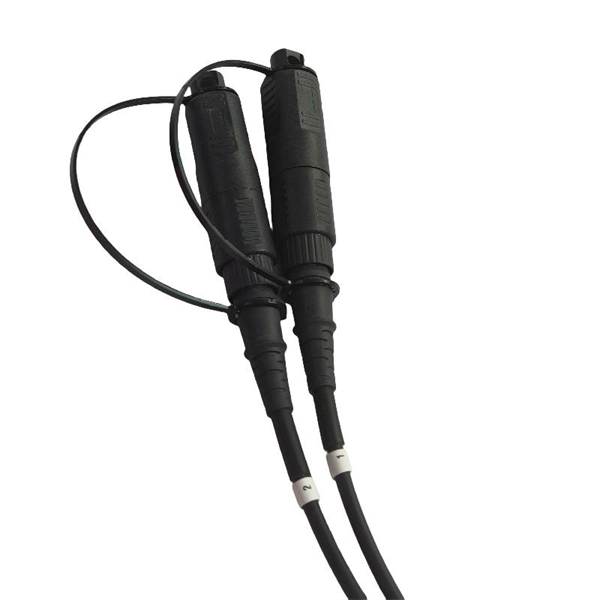
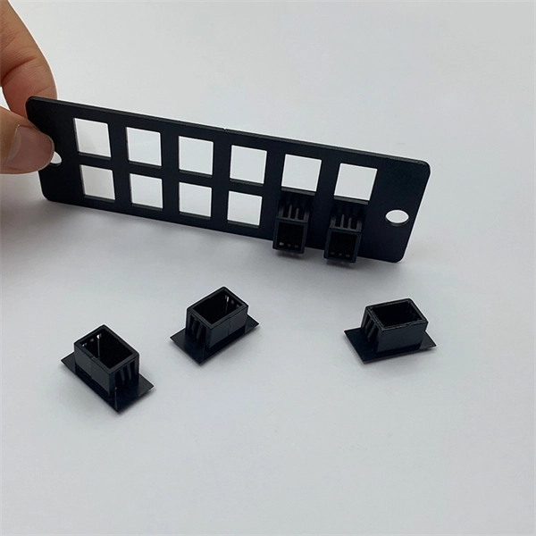
It integrates fiber splicing, splitting, distribution, storage, and cable connection into one unit, providing solid protection and efficient management for building reliable FTTX networks. Total Enclosed Structure: Ensures maximum protection. This fiber optic distribution box serves as a termination point for feeder cables to connect with drop cables in FTTX communication network systems. It is. An optical distribution frame (ODF) is a frame used to provide cable interconnections between communication facilities, which can integrate fiber splicing, fiber termination, fiber optic adapters & connectors and cable connections together in a single unit. It can also work as a protective device. A Fiber Optic Termination Box is a small enclosure located at the terminal end of the fiber where it enters your customer premises. Its function is primarily to splice, secure, and protect the optical fibers connecting the incoming drop cable to the pigtail or patch cable. We separate these products into multiple groups based on application to meet your specifications for mount location and termination capacity.
[PDF]
Shipping cost not included. The 144 core aerial fiber splice closure is a high-capacity outdoor enclosure designed to provide reliable fiber splicing, joint protection, and distribution for aerial and pole-mounted applications. Check each product page for other buying options. Price and other details may vary based on product size and color. Need help?. An Optical Ground Wire (OPGW) splice box is a critical component in power and telecommunications infrastructure, designed to protect and organize fiber optic splices within overhead ground wires. These boxes ensure signal integrity, mechanical protection, and environmental resistance for fiber. ZIP code to view pricing. ZIP code to view pricing.
[PDF]
An aggregation layer usually comprises a few blocks of two switches in MCLAG. By design, it therefore provides resiliency because it will always be deployed in pairs of switches and comes with a recommendation to deploy only dual hot swappable power supplies and redundant fans in each switch to. IEEE 802. 3ad link aggregation enables you to group Ethernet interfaces to form a single link layer interface, also known as a link aggregation group (LAG) or bundle. The LAG balances. Switch-to-Switch Aggregation: This is useful in scenarios where you need to interconnect multiple switches to increase the bandwidth available between them and ensure network redundancy. It helps in managing higher traffic loads between switches. Switch-to-Client Aggregation: This is beneficial. An Aggregation or "Top-of-Rack" switch is designed to connect everything in a rack at high speeds, then have an even bigger pipe out to the rest of the network. The Pro Aggregation does this with it's SFP28 25Gbps ports. While there are many approaches, this article. Would I have any issues if I linked a Ubiquiti aggregation switch to another? We have some fiber runs in our building, but there isn't enough runs to supply all my switch locations and a couple of the runs are too long for 10gig. So, what I want to do is install an aggregate switch at the source.
[PDF]
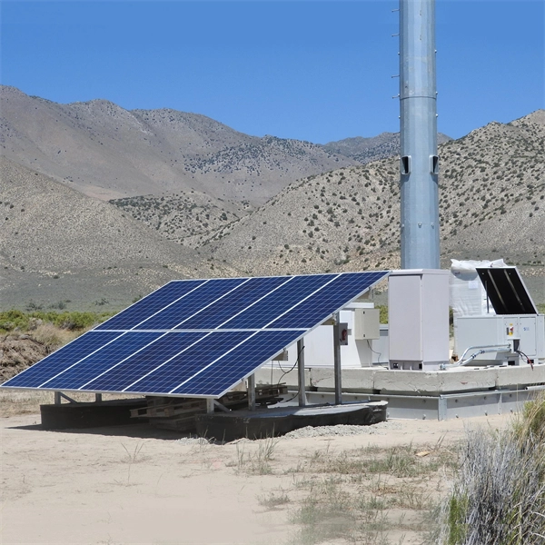
For steel pipe piles, strain sensing FO cables with steel strands are generally installed on the steel pipe surface using welding and cementation. Then the pile is slowly driven into the soil layer. The installatio.
[PDF]
Distributed Fiber Optic Sensing (DFOS) systems, using coherent light pulses, detect physical characteristics such as temperature and strain. DFOS enable localized measurements over long distances, leveraging Rayleigh, Brillouin, and Raman scattering. This review summarizes recent progress and emerging trends in multiparameter optical fiber sensing, emphasizing techniques that enable the simultaneous measurement of temperature, strain, acoustic waves, pressure, and other environmental quantities within a single sensing network. This technology is revolutionizing industries from infrastructure monitoring. Distributed Fiber Optic Sensing (DFOS) systems provide critical asset monitoring by utilizing standard fiber optic cables as sensors. These systems enable precise measurement of temperature, strain, and acoustic signals along the entire length of an optical fiber. Such capabilities.
[PDF]
Fiber optic pressure sensors use light modulation to measure pressure, offering high sensitivity, EMI immunity, and wide-ranging applications. Fiber-optic sensing (FOS) technology has emerged as a cutting-edge research focus in the sensor field due to its miniaturized structure, high sensitivity, and remarkable electromagnetic interference immunity. These sensors are gaining popularity. Fiber optic pressure sensors are generally categorized into two main types: non-interferometric and interferometric. Figure 1 depicts a simplified structure of a non-interferometric fiber optic pressure sensor. Fiber Optic Pressure Sensors work on the.
[PDF]