A ladder type cable tray tee is a fitting used to create a branch in a cable tray system, allowing cables to be routed in three directions. Its "T" shape provides a secure and efficient way to split cables from a main tray into two separate paths, ensuring organized and flexible. A cable tray tee and tee cover are components used in cable management systems to support and protect electrical and data cables. Here's a brief explanation of each:. Rigid steel cable tray tee fitting with zero tangent, safety bottom, and full accessory support. ventilation to heat producing cable such as power communication and other with the same or different width of the cable run. All fittings are available in sizes and types corresponding to the straight cable tray sections. These fitting are including: elbow, horizontal cross, vertical inside. NOTE : Equal or un equal tees can be supplied. When ordering state widths W1xW2xW3.. Office: 147/22 Nguyen Sy Sach Street, 15 Ward, Tân Binh Dist, HCMC,VN. Is it possible to connect 2 cabletrays with a "branch piece (left picture)" instead of a "tee (right picture)". The tee has 3 connectors, the branch piece only has 1 connector. I would like to ajust the "Type properties -> Fittings -> Tee" with the branch family, but can't get it accomplished.
[PDF]

An Optical Splitter, also known as a beam splitter, is a passive optical device that divides a single input optical signal into two or more output signals. Conversely, it can also combine multiple signals into one. Knowing the difference between a splitter and an optical coupler helps you build better networks. You make your network work better when you pick the right device for each job. You can connect many users to one port with 1:n or 2:n splitters. By dividing a single optical signal from a central Optical Line Terminal (OLT) into multiple outputs for Optical Network Terminals (ONTs) at users' homes, splitters eliminate the need for dedicated fibers to each residence—slashing infrastructure costs while scaling network reach. This guide. In a Passive Optical Network (PON), a single optical fiber carries massive amounts of data using light. Signal Input: The fiber splitter receives the optical signal from the upstream network node and enters the splitter through the input fiber. Signal Distribution: Inside the splitter, according to the design structure and different. Splitters are passive optical devices that divide or combine optical signals, and they come in various types, including power splitters, uneven splitters, and wavelength-division multiplexing (WDM) splitters. Each type serves specific applications, enabling efficient use of optical infrastructure.
[PDF]

Cable Trays* — Max two 24 in. (610 mm) wide by max 6 in. (151 mm) deep open-ladder cable tray with channel-shaped side rails formed of 0. 54 mm) thick aluminum or min 0. In practice, cable tray dimensions are a system of interrelated measurements —width, depth, length, and material thickness—that directly affect cable fill compliance, heat dissipation, structural loading, and long-term expandability. From an engineering standpoint, cable tray dimensions are not. Perforated Cable Tray System expertly constructed from high-grade stainless steel, offering exceptional durability and resistance to corrosion. With side height 100mm. A properly designed and installed cable tray system will provide. Studs — Wall framing to consist of wood studs or channel shaped steel studs. Wood studs to consist of nom 2 by 4 in. Additional studs shall be used to completely frame. Best Size: Here, deep trays (75mm to 150mm) are used since power cables are typically thick and heavy. Data cables, such as your Wi-Fi or computer ones, are extremely sensitive. They do not get hot; however, they do not like to hang or sag. In case a data cable folds in an excessive manner, the. ect the minimum bend ra-dius for cables as they exit the bottom of the cable tray. A rung spacing of 6 to 9 inches (150 to 230 mm) is preferable when the cable tray cont d for instrumentation and control applications that require additional protec eferred to support and protect numerous small.
[PDF]
Optical fiber is composed of three elements – the core, the cladding and the coating. These elements carry data by way of infrared light, thus propagating signal through the fiber. The core is at the center of the optical fiber and provides a pathway for light to travel. A TOSLINK optical fiber cable with a clear jacket. These cables are used mainly for digital audio connections between devices. A fiber-optic cable, also known as an optical-fiber cable, is an assembly similar to an electrical cable but containing one or more optical fibers that are used to carry. This is the first in a series of five courses about fiber optic cable systems. The first course, Fiber Optics I –Theory, is an overview of the technology of fiber optic. An optical fiber cable is a complex structure designed to protect fragile glass fibers that transmit digital data using light signals. This advanced cabling solution allows fast, secure data transfer and telecom over long distances. When searching for a fiber optic cable, we need to pay attention not only to the connectors, such as SC to ST fiber cable, LC to SC fiber patch cable, or SC to. This guide explains the structure of fiber optic cables, the most common cable constructions used in the industry, and how to choose the right cable type for indoor networks, outdoor deployments, data centers, and FTTH systems. In multimode fiber, the.
[PDF]

The three-layer structure in the core, which is composed of a core-index layer, a cladding-index layer, and a depression-index layer, could achieve a large effective area Aeff while maintaining an ultralow bending loss without deteriorating cutoff behaviors. Optical fiber sensors have been potentially expected to apply in the extreme environment for their advantages of measurement in a large temperature range. The packaging measure which makes the strain sensing fiber survive in these harsh conditions will commonly introduce inevitable strain transfer. A three-layer-core single-mode large-mode-area fiber is investigated. It's a device that converts light rays into electronic signals. Think of it like a photoresistor, which changes its resistance based. The review summarizes numerical technique employed simulations of optical fiber plasmonic sensors (OFPS) based on fiber types, probe geometry, metal-dielectric film, and nanostructures. The recent progress in nano-optics has developed susceptible and label-free optical devices by using SPR/LSPR.
[PDF]
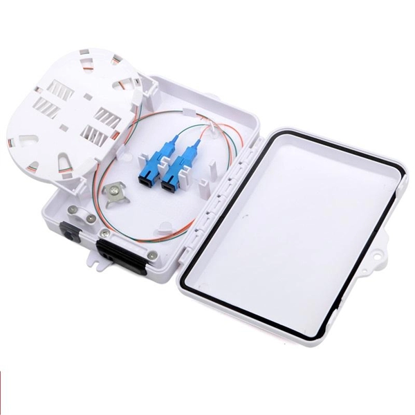
Wall-mounted fiber distribution frames are typically designed as box-like structures, ideal for locations with fewer cables and fiber cores. Whether you're building a central office, data center, or FTTx distribution network, understanding the right ODF. FDF, or Fiber Distribution Frame, is a key component used for the termination, utilization, and management of optical cables between wiring rooms and equipment rooms. In structured cabling systems, ODFs are suitable for horizontal cabling between equipment or their terminations, as well as. A distribution boxes is an essential device that manages the safe and efficient flow of electrical power throughout different areas of a building or facility. It is commonly used in homes, offices, and industrial settings to control and protect electrical circuits. Understand its role in electrical systems and safety.
[PDF]

Distribution boards, often referred to as electrical panels or breaker boxes, serve as the nerve center of any electrical system. These essential components play a pivotal role in managing and distributing electrical power within a building or facility. Some old breaker boxes pose serious safety concerns. Many were not manufactured up to safety standards from the beginning. During World Wars I & II, manufacturers used inferior aluminum metals for bus bars. Over time they have been proven to overheat, making them dangerous and unsafe. The typical. What is a Distribution Box? A distribution box, or DB box, is a circuit breaker enclosure. The hub distributes electrical power from a single input source to various circuits throughout a building. Whether it's a home, office, or factory. What Is a Distribution Box? Types, Uses & How to Choose What Is a Distribution Box? Types, Uses & How to Choose A distribution box, also known as a power distribution box or electrical distribution box, is used to distribute electrical power safely to multiple circuits. Inside, you'll find parts like circuit breakers and fuses that protect the system from problems like overloads and short circuits. In this comprehensive guide, we will explore. Electrical systems power our homes, offices, and industrial facilities, but behind every reliable electrical setup lies a crucial component that often goes unnoticed: the distribution box.
[PDF]
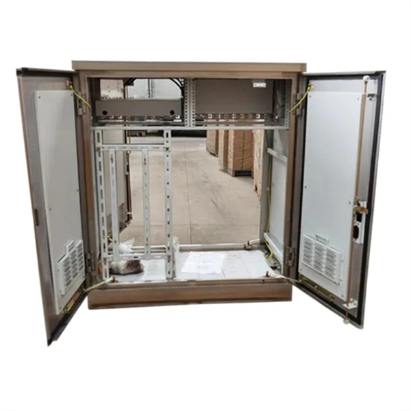
The photovoltaic combiner box shell structure plays a critical role in protecting electrical connections from environmental hazards. This article explores design principles, material choices, and industry trends to help professionals optimize their solar installations. A solar combiner box is a crucial component in solar energy systems, designed to consolidate the outputs of multiple solar panel strings into a single output that connects to an inverter. This device plays a significant role in both residential and commercial solar installations, particularly when. This guide explains how combiner boxes work, how they have evolved, how to select the right model, and what future trends will shape the next generation of solar infrastructure. Each. Solar energy systems rely on robust components to ensure efficiency and safety. This comprehensive guide aims to shed light on the importance, functions, types and best practices of combiner boxes, unlocking the mystery behind their role in harnessing solar energy. In a photovoltaic system, a combiner. A PV combiner box is installed at the system level. Its primary purpose is to combine multiple PV strings into a smaller number of outputs before power goes to the inverter or another downstream device. It is equipped with fuses or circuit breakers to protect each.
[PDF]

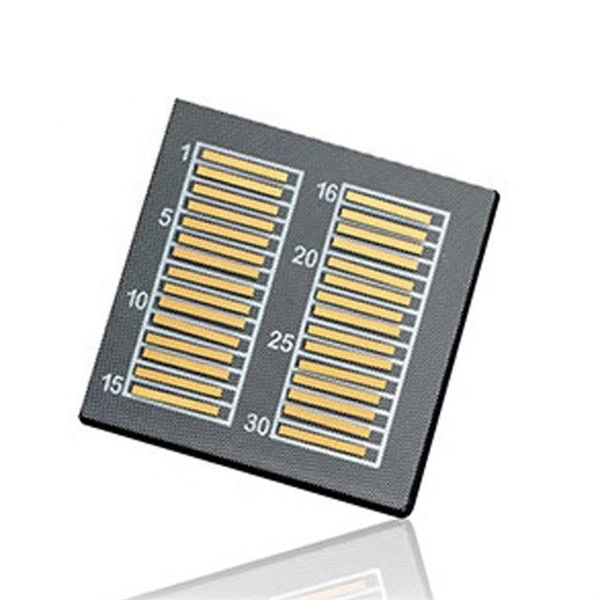
The optical module is usually composed of Transmitter Optical Subassembly (TOSA, containing a laser LD Chip), Receiver Optical Subassembly (ROSA, containing a photodetector PD Chip), a driving circuit, and an optical and electrical interface. Its schematic is shown in. This section explains the structure of a typical pigtail butterfly module, which gets its name from the two rows of seven leads at right angles on each side of the metal package plus an optical fiber pigtail at one end (Fig. Let's look at the internal structure (Fig. 2) of a common butterfly. Optical modules are devices used to connect network devices, transmit and receive data between network devices, and can be used to convert optical and electrical signals. The optical module is a very important component in an optical communication system. Optical devices are the core components of optical modules. TOSA and ROSA in Common Optical Transceiver Modules For ordinary optical transceiver modules, there are two optical devices, TOSA and ROSA, which have opposite effects.
[PDF]

This comprehensive guide breaks down the internal structure, core components (TOSA, ROSA, lasers), and operational mechanisms of SFP optical modules, enriched with technical insights and real-world applications. SFP (Small Form-factor Pluggable) optical modules are compact, hot-pluggable transceivers that enable network equipment to connect seamlessly to fiber and copper links. As a leading provider of optical communication solutions, Weunion integrates these. One vital element in the data communication sector is the Small Form-factor Pluggable (SFP) module. In this blog, we will explore the inner workings of these modules, with a particular focus on three essential optical components: TOSA, ROSA, and BOSA. SFP modules are small, hot-swappable devices. Optical modules are devices used to connect network devices, transmit and receive data between network devices, and can be used to convert optical and electrical signals. The optical module is a very important component in an optical communication system. Think of it as the “translator” for your network equipment, converting electrical signals into optical signals. available with a variety of types of copper SFP and fiber SFPs, SFP+. This transceiver module is compliant wi h the small form-factor pluggable (SFP) multi-source agreement (MSA). They industrial performance with an extended operating temperature range. Through real-time monitoring, the DDM.
[PDF]