Distributed Fiber Optic Sensing (DFOS) systems, using coherent light pulses, detect physical characteristics such as temperature and strain. DFOS enable localized measurements over long distances, leveraging Rayleigh, Brillouin, and Raman scattering. This review summarizes recent progress and emerging trends in multiparameter optical fiber sensing, emphasizing techniques that enable the simultaneous measurement of temperature, strain, acoustic waves, pressure, and other environmental quantities within a single sensing network. This technology is revolutionizing industries from infrastructure monitoring. Distributed Fiber Optic Sensing (DFOS) systems provide critical asset monitoring by utilizing standard fiber optic cables as sensors. These systems enable precise measurement of temperature, strain, and acoustic signals along the entire length of an optical fiber. Such capabilities.
[PDF]

The main components of a splice box are the splice cassette that picks up the fibers and their reserves, and the front panel which contains different connectors for transmitting signals via copper or fiber optic cables. A splice box (also known as splice distributor) is a housing in which fiber optic cables begin or end. Fiber optics are fanned out in splice boxes that are situated at the end of fiber optic transmission paths. It typically consists of two parts: an outer housing and an internal structure. In this response, we will focus on the. The FSB series of indoor wall mount enclosures are designed for centralized splice-only applications. These boxes are well suited as optical cable splice collection points for DAS (Distributed Antenna Systems), MTU (Multi-Tenant Unit) commercial business applications, and MDU (Multi-Dwelling Unit). Fiber optic splice closures permanently connect two fiber optic cables together and have a splice that protects the components. The optical cable connection part, that is, the optical cable joint, is the part that protects the connection between two or more optical cables by the optical cable. Splicing refers to the permanent connection of two optical fibers to form a continuous optical connection.
[PDF]
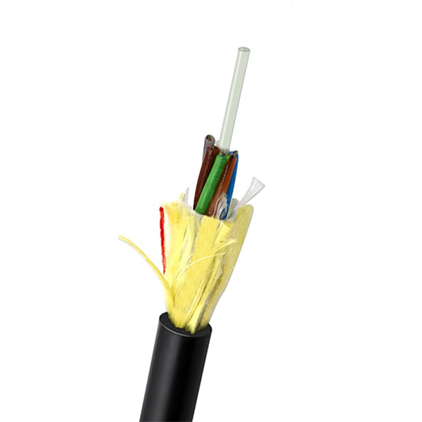
GJXFH FTTH Indoor Drop Cable uses butterfly flat structure, whose optical fiber unit is positioned in the centre. Two parallel Fiber Reinforce Plastic (FRP) strength members are placed at the two sides. Then, the cable is completed wit. GJXFH FTTH Indoor Drop Cable uses butterfly flat structure, whose optical fiber unit is positioned in the centre. Two parallel Fiber Reinforce Plastic (FRP) strength members are placed at the two sides. Then, the cable is completed with LSZH sheath. FTTH indoor cable has a much greater bandwidth to carry data and less susceptible to interferenc. Central loose tube cables and self-supporting FTTH drop cables are desinged for outdoor aerial distribution. With non-metal strength member, suitable for access network a n d l o c a l n e t w o r k i n h i g h electromagnetic interfering places. Armored FTTH duct cables are made for connecting user's devices with outdoor feeder cable, especially suitable for duct installation. It features good waterproorf and anti-rodents performance. Soft and flexible, good bending performance Easy to installation, handling and maintenance Good waterproof and flame retardant performance Specially used in the FTTH projects- indoor/outdoor installations. With simple installation, FTTH indoor cables can be directly connected to the homes. They are suitable for c o n n e c t i n g c o m m u n i c a t i o n equipments, and used as access building cables in premise distribution system. FTTH Fiber Cable.
[PDF]

The number of optical cores in an optical fiber is the total number of equipment interfaces multiplied by 2, plus 10% to 20% of the spare quantity, and if the communication mode of the equipment has serial communication and equipment multiplexing, you can reduce the number of cores. The number of. Fiber cores are the heart of fiber optic cables, transmitting light signals that carry data. Made from either high-quality glass or plastic, the core plays a critical role in determining the cable's performance. The total number of cores for a 1pc fiber patch cable is calculated as the number of. Common fiber cores include 1 core, 2 cores, 6 cores, 8 cores, etc., and there are many types. This article will focus on the number of fiber cores, introducing their respective characteristics and usage scenarios. When selecting fiber, the first step is to determine single mode or multimode, and. Fiber optic cables consist of multiple thin strands of glass or plastic, known as “cores. ” These cores carry the data signals via light. • Design engineers reserve spare fibers for potential breaks and future upgrades to the system. • Anticipating future growth during cable installation proves.
[PDF]
Optical fibers can be used as sensors to measure, , and other quantities by modifying a fiber so that the quantity to be measured modulates the,,, or transit time of light in the fiber. Sensors that vary the intensity of light are the simplest, since only a simple source and detector are required. A particularly useful feature of intrinsic fiber-optic sensors is that they can, if required, provide distributed sensing over very large distances.
[PDF]

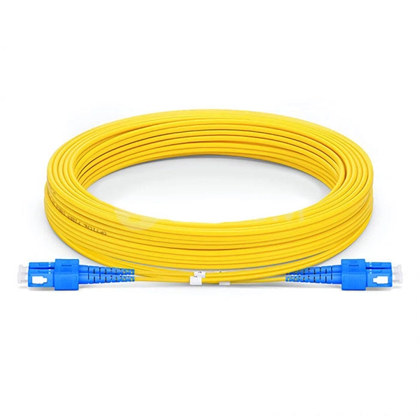
Fiber optic pigtails are short, single, or multi-strand pieces of optical fiber cables with a connector on one end and exposed fiber on the other end. They are typically used to terminate fiber optic cables and connect them to patch panels, equipment, or other termination points. Fiber pigtails are simple in appearance, yet essential in function. Despite this ubiquity, they remain a source of confusion for procurement teams and junior installers alike—especially when it comes to connector type selection, polish type, and the tradeoffs between mechanical. Fiber Optic Pigtails, also known as pigtailed fibers, consist of an optical fiber connector and a section of optical cable. Characterized by having an optical fiber connector on one end and a bare fiber end on the other, they are primarily used to connect optical transceivers or other optical. A Fiber Optic Pigtail Complete Guide: As per types, connectors, and applications. In such contemporary fiber optic communication systems, low-loss, and connectivities, which have reliability, are crucial for not only maintaining high-speed but also high-quality data transmission. It is usually suitable for field termination using a mechanical or fusion splicer. Compared with quick termination or epoxy and polish connections placed on the field.
[PDF]

Receiver sensitivity is the lowest optical power level at which an optical receiver can successfully decode data with acceptable bit error rates (BER). It's a core parameter in optical transceiver specifications, indicating the module's capability to detect weak incoming signals. The standards body governing the application sets this specified BER. For example, SONET specifies that the BER must be 10 -10 or better. What Is BER? The bit error rate (BER) measures the data transmission precision within. Receiver sensitivity stands as a critical parameter impacting an optical transceiver's functionality. It denotes a module's capability to function in challenging environments and aids network operators in determining the system's maximum reach or link margin. Lower receiver. Among a group of optical receivers, a receiver is said to be more sensitive if it achieves the same performance with less optical power incident on it. The performance criterion for digital receivers is governed by the bit-error rate (BER), defined as the probability of incorrect identification of.
[PDF]
Horizon Databook provides a detailed overview of country-level data and insights on the UAE distributed fiber optic sensor market, including forecasts for subscribers. The Distributed Fiber Optic Sensor Market in the UAE is growing due to the applications of this technology in various sectors, including infrastructure monitoring, oil and gas, and environmental sensing. Distributed fiber optic sensors offer the ability to monitor large areas with high precision. United Arab Emirates (UAE) Fiber Optic Sensors Professional Market Global Outlook, Country Deep-Dives & Strategic Opportunities (2024-2033) Market size (2024): USD 1. 2 billion · Forecast (2033): 2. A compound annual growth rate of 11. The UAE distributed fiber optic sensor market generated a. A Fiber Sensor is a type of photoelectric sensor that enables the detection of objects in limited locations by transmitting light from a fiber amplifier unit with a fiber unit. Fiber optic unit working principles are fallen into three categories as follows; Through-beam sensors: The emitter and. AI-driven workflow optimization is revolutionizing the UAE fiber optics sensor market by enabling manufacturers and service providers to enhance operational efficiency through predictive maintenance, real-time monitoring, and adaptive network management. The market is characterized by a diverse ecosystem comprising technology providers, system integrators, end-user industries, and.
[PDF]

Fusion splicing is the process of fusing or welding two fibers together usually by an electric arc. Fusion splicing is the most widely used method of splicing as it provides for the lowest loss and least reflectance, as well as providing the strongest and most reliable joint between. This guide reveals the secrets to fusion splicing with little fluff—just proven, straightforward techniques refined from years of work in the field. The goal is to fuse the two fibers together in such a way that light passing through the fibers is not scattered or reflected back by the splice, and so that the splice and the region surrounding it are almost as strong as the. A fusion splicer is a specialized tool used in fiber optic networks to join two fiber optic cables together permanently. This process creates a strong and reliable connection that can withstand. Splicing fiber optic cable is an extremely important phase for making dependable, high-speed communication infrastructures. Fusion splicing stands out as a superior technique for joining optical fibers, offering a seamless, low-loss connection that is crucial for reliable fiber optic networks. Let's explore the fundamentals of mechanical and fusion.
[PDF]

Typical rates range from $0. 00 per ft depending on terrain, access, and required precision for termination. Basic — 1,000 ft single-mode run indoors with minimal termination: Cable $0. 00/ft, Permits $150, Accessories $100. Total ≈ $2,650–$3,100. Fiber-optic cable materials typically cost $1 to $6 per linear foot, depending on fiber count and cable type. Commercial building installations with 100-200 network drops generally range from $15,000 to $30,000. Single-mode fiber costs less per foot than multimode fiber, but it requires more. Buyers typically pay for fiber optic cable by length, fiber type, and installation complexity. Main cost drivers include cable grade (indoor vs outdoor, armoured), distance, and labor for trenching, splicing, and termination. This guide presents ranges in USD and practical price estimates to help. The cost per foot of fiber optic cable is now the lowest it's been since 2021. Labor dominates the installed price. Here is the 2026 benchmark for cost of laying fiber optic cable per foot by method: Open trench (lawn/field): $0. 80 per ft – fastest, lowest cost. Directional boring (road. Single-mode fiber (OS2): This is the industry workhorse. In 2025, the base glass price has stabilized. You are looking at $0. The price swing usually depends on the fiber count (e., 12-core vs 96-core) and brand. This article breaks down the price landscape and provides.
[PDF]

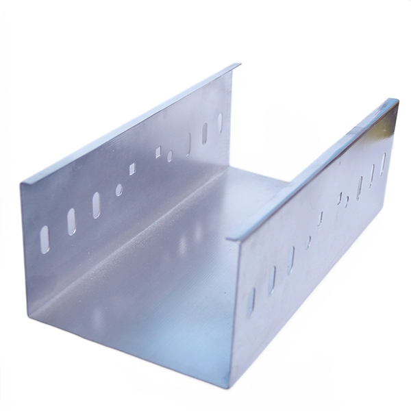
This helps keep fiber optic cables safe from harm and signal problems when you put them in. Use the right lubricant. Follow the rules for tension and bend radius. Try new methods like air blowing. Use smart. Fiber optic cable is surprisingly strong, durable and pliable; however, several best practices should be followed to ensure a successful cable installation. This article explores recommendations for pulling and installing fiber optic cable. This makes sure the cable pull is smooth and safe. Use smart monitoring devices. The Future Ready Solutions Tools & Test. A duct is available from point A to point B, a pull tape is blown in, a fiber optic cable is attached to it and the cable is pulled through the duct. Sounds simple, doesn't it. Recent observations and conversations with more than a few people in the fiber optic business have indicated. Route plan to ensure the duct run maintains the minimum bend diameter of the cable. For more information and all recommendations for installation, refer to Corning Optical Communications Standard Recommended Procedure SRP 005-011, "Duct Installation of Fiber Optic Cable". more Route plan to ensure.
[PDF]

Contrary to popular belief, fiber optic cables do not contain copper. Instead, they consist primarily of glass or plastic fibers that transmit data using light signals. These fibers are surrounded by protective coatings made of materials such as polymer or epoxy resin. Fiber optic cables are designed to provide high-speed, no-signal-loss, and EMI-free communication in telecommunication, powergrid, datacenter, broadband, and industrial applications. Each optical cable is constructed using a precise combination of optical fibers, strength members, buffer tubes. Fiber optic cables use pulses of light through ultra-pure glass or plastic fibers to carry information rather than electrical signals. Cladding: Lower refractive index layer reflecting light back into. You might wonder if there's copper inside fiber optic cables. It's not a yes-or-no answer. So, it's about knowing the different types. Its primary method of data transmission relies on light signals traveling through glass or plastic fibers, rendering copper conductors unnecessary for that purpose. Fiber optic cables have revolutionized data transmission. The two core material technologies used in almost all cables are fiber optic, and copper wiring.
[PDF]

Here's a step-by-step guide to help you set up your fiber distribution box seamlessly: Before installing the fiber distribution box, ensure that your optical cables are properly prepared for connection. The optical fiber distribution box allows people to easily access the optical fibers in the box, and can well protect the optical fibers. In addition, the drawer structure also facilitates high-density wiring and good cable management. However, because optical fibers are fragile and can be easily. Keeping this page as a placeholder for now. Have any questions? Talk with us directly using LiveChat. Fix the rack to the ground with expansion bolts. Top installation: Dimensions of four connection holes on the top according to the. This instruction describes the installation of the Fiber Distribution Frame (FDF) manufactured by Corning Optical Communications. To order accessories that are purchased separately, contact Corning Optical Communications customer care for assistance. Read and understand this procedure (as well as. Optical fiber distribution frame is the wiring connection equipment between optical cable and optical communication equipment or between optical communication equipment. Distribution boxes are especially essential for FTTH networks, where they enable the efficient connection and management of optical fibers from a central.
[PDF]

Arduino-Powered Data Transmission with Fiber Optics Welcome to our video tutorial on optical communication with Arduino, designed to be easy t. more. They consist of a transmitter on one end of a fiber and a receiver on the other end. Most systems use a "transceiver" which includes both transmission and. I'm going to use HFBR 1414 fiber optic transmitter module which is manufactured by Broadcom. It is a low-cost high-power transmitter that is designed for use in industrial power generation, power distribution, medical transportation and gaming applications. Internally, the optical fiber consists of a highly reflective central core, which acts like a light guide. Media converters are special fiber optic transceivers used to convert from one type of cable (the media) to another, typically from copper cables to fiber optics, although some media converters will convert from one fiber type to another, e. multimode to singlemode. The FOA Guide has a page about. A fiber optic transceiver (also called an optical transceiver) is a compact module that both transmits and receives data signals through optical fibers. It serves a dual purpose — transmitting electrical signals as light pulses and receiving light pulses to convert them back into electrical form.
[PDF]

The basic structure of optical fiber consists of three primary components: the core, the cladding, and the buffer coating. The core is the central part of the optical fiber through which light is transmitted. An optical fiber cable is a complex structure designed to protect fragile glass fibers that transmit digital data using light signals. This advanced cabling solution allows fast, secure data transfer and telecom over long distances. Understanding the components within a fiber optic cable enables. In this blog, we will delve into the fundamental components and structure of optical fiber to gain a better understanding of this revolutionary technology. At its core, optical fiber is a thin, flexible, and transparent fiber made of glass or plastic, which serves as a medium for transmitting light. They consist of three main components and are available in several structures suited to different uses. In this article, discover in detail these components and the various structures of fiber optic cables. The core: made of silica, molten quartz, or plastic, in which optical waves propagate. Dielectric material conducts.
[PDF]