The 3R A3140 AA serves as a fully compatible, drop-in replacement for the HCPL-3140, featuring matched performance metrics including propagation delay, CMTI, and output current, ensuring dependable real-world implementation in industrial and automation settings. The HCPL-3140/HCPL-0314 family of gate driver optocouplers consists of an GaAsP LED optically coupled to an integrated circuit with a power output stage. These optocouplers are ideally suited for driving power IGBTs and MOSFETs used in motor control inverter applications. The high operating voltage range of the. 0. Here you can find various types and values of electronic parts from the world's leading manufacturers. The HCPL-3140/A3140 components of Jotrin Electronics are carefully chosen, undergo stringent. The HCPL-3140-000E is a 0.
[PDF]

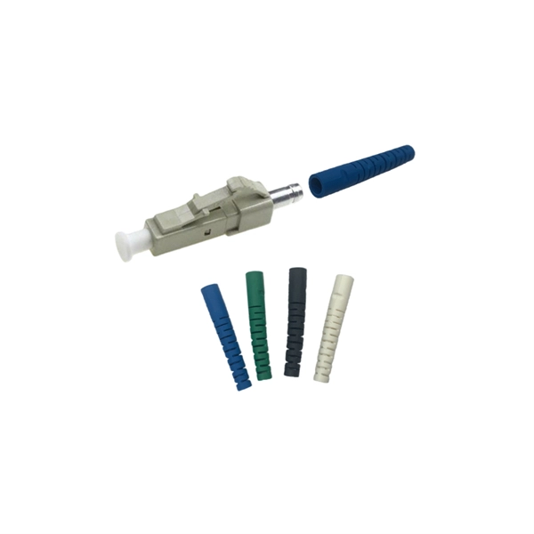
This installation note provides the installation instructions for the Cisco small form-factor pluggable (SFP) and SFP+ transceiver modules. This document is intended to serve as a guide for architecting and deploying fiber optic networks in a customer environment. These transceiver modules are hot-swappable input/output (I/O) devices that plug into 100BASE, 1000BASE and 10GBASE ports (for SFP+), which connect the module. This manual provides safety and installation instructions for the 9490-OS Fiber Optic Passive Splitters. All units use type LC connectors and vary only in the splitting fan-out, and as single or dual-channel capability as listed below. Optical fibers require special care during installation to ensure reliable operation. Installation guidelines regarding minimum bend. Listings and approvals under Time Recorder Co. are the property of Tyco Fire Protection Products. Description Multiple Signal Fiber Optic Modems combine multiple system communications signals and convert them to fiber optic communications for transmission. This guide will focus on the 1x9 dual SC optical transceiver products. Pin Assignment & Description TD+, TD: DC coupled LVPECL inputs for the transmitter.
[PDF]

This publication shows how to wire and install the 4010-9825 24V Distribution Block into a 4010 Fire Alarm Control Panel (FACP). Refer to the 842-058 Field Wiring Diagram for additional wiring information. 1 Transformer connection: Two red wires connect to AC 220V input port, while two yellow wires connect to AC input port of main board (had connected by the factory. 2 DC12V battery connection: Red wire on the circuit main board connects to the positive pole of acid-lead battery while black. Notify the carrier and call Telect's Customer Service Department at 1-800-551-4567. Keep the container until you have checked equipment operation. Use the original, undamaged container if you are instructed to return. Learn how to wire a distribution box step by step! This video shows real on-site footage of electrical installation, demonstrating safe and standardized wiring methods used by professionals. Such a system, however, does not assure. Material preparation: Prepare the required circuit breakers, wires, wiring ties and other materials, and ensure that they meet the design drawings and installation requirements. Location determination: Determine the installation position of the circuit breaker according to the position of the.
[PDF]

In this tutorial, I will show you how you can connect the Optocoupler to Arduino, read the data as Analog or Digital, and if necessary convert the analog values to digital, and how to reduce noise from the sensor. The Infrared Slotted Optical Optocoupler Module is a device that uses infrared light to transmit signals between two electrically isolated circuits. It consists of an infrared emitter (LED) and a photodetector (phototransistor) housed in a slotted enclosure. When an object passes through the slot. Slotted Optocouplers (Photo Interrupters) are very useful sensors, often included in Arduino projects to detect position of moving objects, measure speed of rotation, or linear motion, frequency of events, and many others. They are easy to use, but it is important to understand how they work, so. This tutorial is a comprehensive, practical guide to the Speed Sensor / Tacho Sensor (Slot-Type Optocoupler) (Leobot Product #245). Moreover, a simple application is programmed that shows how to wire and how to program an Arduino when working with the module. In this tutorial, the module is used as an “digital input board”. If you want to use the. In this project, I will talk about Phototransistor Optical Interrupter Switches (Opto Coupler) Module, how this module works and helps in determining the speed of a rotating object and finally I will show you how to Interface Optical Interrupter Switch Sensor with Arduino and measure the speed of a.
[PDF]
The CFP, short for C form-factor pluggable, is a multi-source agreement to define the form-factor of the optical transceiver for high-speed digital signal transmission. CFP transceivers are defined by CFP MSA to enable 40 Gb/s, 100 Gb/s and 400 Gb/s applications. The c stands for the Latin letter C used to express the number 100 (centum), since. What is a CFP optical module? Is it still relevant in 2026? And when should you choose it over newer alternatives? This guide is designed to answer those questions with clarity and technical depth. In this comprehensive article, we will delve into the world of CFP optical transceiver modules, exploring their. What is CFP Modules? Complete Guide to Standards, Variants, Comparisons, and Applications What is CFP Modules? Complete Guide to Standards, Variants, Comparisons, and Applications What is CFP Modules? Complete Guide to Standards, Variants, Comparisons, and Applications In the era of cloud. This article breaks down the key differences between CFP, CFP2, CFP4, and CFP8 optical transceivers commonly used in fiber optic networks. Figure 1: Dimensions of CFP, CFP2, CFP4, and CFP8 The table below summarizes the specifications of each form factor: 24 W (Max. ) In essence, the progression.
[PDF]
An optical module housing is the protective outer shell that encloses the internal components of an optical transceiver module. Optical modules (SFP, SFP+, QSFP) are small, but when multiplied by thousands of ports they become a meaningful line item in both energy and heat budgets. These modules are essential for converting electrical signals into light signals and vice versa, forming the backbone of fiber. However, when it comes to optical transceivers, cutting costs blindly can lead to compatibility issues, link failures, and unexpected downtime. So the real question is: 👉 How can you reduce optical module costs while maintaining reliability and performance? This guide breaks down practical. As an essential component of optical fiber communication, optical modules are optoelectronic devices that facilitate the conversion between optical and electrical signals during the transmission process. Operating at the physical layer of the OSI model, optical modules are core devices in optical. Optical modules are electronic devices that convert electrical signals into optical signals for transmitting data over an optical fiber. The internal structure of an optical module is complex but can be divided into several main parts.
[PDF]

Its typical transmission distance is 20km or 40km. For instance, some ethernet switch manufacturers refer to the 1000BASE-LH SFP as the 1G 1310nm 40km SFP transceiver, which indicates the module's transmission distance and wavelength. The 10G SFP+ dual-fiber optical module is a small pluggable optical transceiver that adopts a dual-fiber bidirectional design. It completes signal transmission (Tx) and reception (Rx) through two independent optical fibers, ensuring the stability and reliability of signal transmission. An SFP (Small Form-factor Pluggable) module transmits data over fiber using specific wavelengths and power levels, which directly influence how far the signal can travel before degradation occurs. This is why two. If the optical module works at a wavelength near 850nm (880nm) or 910nm (940nm), then the module is a multi-mode fiber (MMF) optical transceiver, and if the working wavelength is 1310nm or 1550nm, it is a single-mode fiber (SMF)optical module. Generally, the maximum transmission distance(generally. The transmission distance of optical transceiver modules is divided into short distance, medium distance, and long distance. A 1-core module uses a single fiber core for data transmission, while a 2-core module uses two cores. o Think of a highway. Chromatic dispersion This is a key factor affecting single mode fiber distance.
[PDF]
Click to get your 800G transceiver modules and cables from nearby warehouses. 30-Day Free Return. Trusted by 260K+ Enterprise Users. Cisco QSFP-DD and OSFP 800G ZR/ZR+ digital coherent optics modules enable 800G traffic over amplified Dense Wavelength-Division Multiplexing (DWDM) links up to 120 km for 800ZR and over 1000 km for 800G ZR+. Our sales manager will contact you soon. High-density 800G OSFP and QSFP-DD transceivers support InfiniBand and RoCE, enabling 100m to 2km transmission via MMF and SMF. Know how QSFPTEK make sure your order gets to you on time. Review your item's return/exchange eligibility or warranty period. Select reliable payment options for quick and easy transactions. View the daily routine of QSFPTEK's high-spec production chain. QSFPTEK is a leading high-tech company which. The Forara 400G OSFP, 400G QSFP-DD and 200G QSFP-DD products are hot-pluggable, high-density and low-power, designed for use in 400 Gigabit Ethernet and 200 Gigabit Ethernet links over data center, high-performance computing networks, enterprise core and distribution layers, and service provider. Connlight's product specification covers the performance of the OSFP to QSFP-DD Adaptor Module that offers 800 Gigabit Ethernet transfer to 400、200、100 or 40 Gigabit Ethernet connectivity for OSFP only. it allows smooth and cost-effective migration to 800 Gigabit Ethernet by providing an option to.
[PDF]
Read the topics and perform the procedures in this order: 1. Preparing for Installation 2. Planning a Switch Data Stack 3. Installing and Removing an SFP and SFP+ Module 6. Where To. The following information is for FCC compliance of Class A devices: This equipment has been tested and found to comply with the limits for a Class A digital device, pursuant to part 15 of the FCC rules. These limits are designed to provide reasonable protection against harmful interference when the. What Can I Do If a Message Is Displayed Indicating that an Optical Module Is Not Supported During Stack Port Configuration? - S300, S500, S2700, S5700, and S6700 V200R023C00 Configuration Guide - Device Management - Huawei How Do I Install a License File for a Stack System? How Do I Specify a. Page 1 Catalyst 3650 Switch Hardware Installation Guide April 2016 Cisco Systems, Inc. com Cisco has more than 200 offices worldwide. Addresses, phone numbers, and fax numbers are listed on the Cisco website at www. Text Part Number: OL-29734-01. Page 2 OR ITS. This guide describes the hardware features of the Catalyst 3650 switches. It describes the physical and performance characteristics of each switch, explains how to install a switch, and provides troubleshooting information. This guide does not describe system messages that you might receive or how.
[PDF]
We supply 1X9 Single Mode Fiber Optical Transceiver and 1X9 Multi mode Fiber Optical Transceiver, RoHS compliant fiber optic transceiver modules. 1x9 optical transceiver modules are state-of-the-art components designed expressly for the building of high-speed bi-directional communication links that require data rates of up to 1. The modules operate at special extended voltage and temperature (-10 to 85 C) ranges. 1x9 optical. North America Fiber Optics (NAFO) is the sole distributor of Coretek Opto, a leading fiber optic transceiver and optical component manufacturer based in Taiwan. Coretek offers a comprehensive portfolio of high-quality optical products ranging from legacy optical modules to next-generation. 1x9 transceivers are the earliest and oldest-style optical modules. Initially created in the 1990s, they aimed at 100M/1G Ethernet, Fibre Channel, ATM, FDDI, SDH/SONET, and video applications. Then, they were gradually replaced by more advanced and intelligent GBICs, SFPs, SFP+, and QSFPs. 9-pin DIP transceivers for very-legacy switches built before the SFF/SFP standards. Replaces discontinued Methode / Stratos / Optech parts. The original optical module form factor (mid-1990s). It is usually directly cured on the circuit board of the communication equipment and used as a fixed optical module. The 1X9 optical transceiver module can be divided. You are here: Home >> Product >> Optical Transce. >> 1X9 Transceiver.
[PDF]
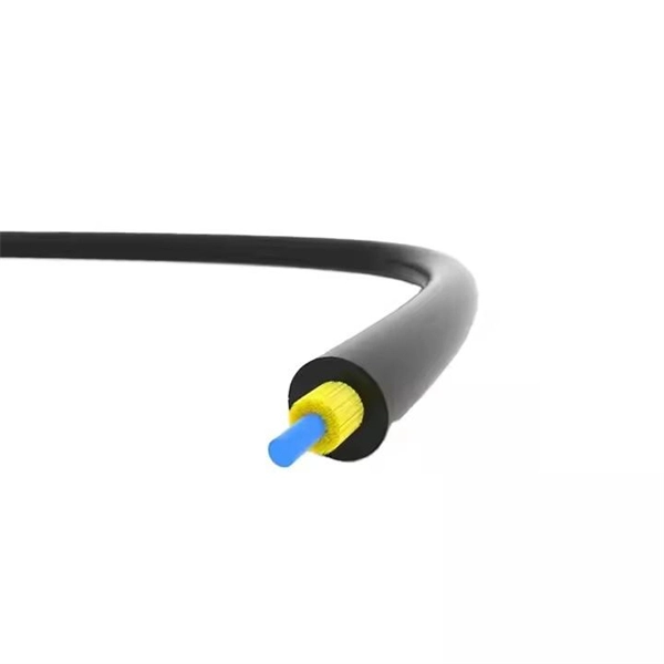
It is designed to transmit data in one direction only. The single-mode optical fiber is designed and engineered to carry one single light mode in a minimal core diameter. It is specified as the best for especially long-distance applications than multimode fiber. Higher-order modes like LP 11, LP 20 etc. Modes are the possible solutions of the Helmholtz equation for waves, which is obtained by combining. Simplex fibers are most commonly used in applications that only require data transmission in one direction. Digital data readouts, interstate sensor relays, and automatic speed and boundary sensors (for sports applications) are all important uses for simplex fiber optic cables. It is designed to. Simplex single-mode fiber is typically used in scenarios where data only needs to be sent in one direction, such as in sensor application like a fire alarm system that sends signals from detectors to a control panel might use simplex fiber. Duplex single-mode fiber is commonly used everywhere else. Single fiber modules (BiDi) use one fiber for both transmitting and receiving data. This saves space and money. Dual fiber modules use two fibers.
[PDF]

Average Optical Power: How bright the light is (measured in dBm). Too dim? Your signal gets lost in the fiber. Extinction Ratio: The difference between “on” (1) and “off” (0) light power. A higher ratio = cleaner signals. Transmitter Side: An electrical signal hits a laser diode (LD) or LED, which spits out light. Receiver Side: Light enters a photodetector (like a tiny solar cell), which turns it back into electricity. A built-in amplifier boosts the signal for your. The average transmitted optical power refers to the optical power output by the light source at the transmitting end of the optical module under normal working conditions, which can be understood as the intensity of light. In communication, we usually use dBm to represent optical power. However, in practical use, we adopt the average Tx power. The transmission power is related to the. This article provides an in-depth analysis of two key performance indicators of optical modules: transmitter power and receiver sensitivity. Transmitter power characterizes the average optical power output from the laser under rated conditions, while receiver sensitivity indicates the minimum. An optical module is a connecting module that serves as an optical-electrical conversion device. At the receiver end, the optical signals are reconverted into electrical.
[PDF]
The main trade show for the large optical module industry is the Optical Fiber Conference (OFC), that is held annually in southern California. Other prominent shows for the industry include ECOC in Europe and FOE in Japan.
[PDF]

Learn how to monitor SFP optical power on Cisco switches, interpret Tx/Rx levels, and troubleshoot fiber link issues. Step-by-step CLI commands, model-specific guidance, and best practices included. In this article, we will break down the key factors influencing TX/RX power, explain how to calculate the optical power budget, and provide actionable insights for optimizing your network's performance using SFP modules. SFP (Small Form-Factor Pluggable) modules are compact transceivers that allow. SFP (Small Form-factor Pluggable) optical modules are compact, hot-pluggable transceivers that enable network equipment to connect seamlessly to fiber and copper links. Even if an interface appears up, degraded Tx/Rx levels can cause intermittent flapping, packet loss, or err-disabled states. Think of it as the “translator” for your network equipment, converting electrical signals into optical signals. The most two important factors of the SFP transceiver: Output power (TX power) and receiver sensitivity (RX sensitivity). The optical TX power is the signal level leaving from that device, which should be within the transmitter power range. The RX sensitivity is the incoming signal level being. In current network communication, SFP optical modules are an indispensable physical foundation for building network channels. They form high-speed channels for optical signal transmission. Therefore, to ensure their.
[PDF]

If the optical module is faulty, replace it with the spare part. If the fault is caused by the configuration or environment, advise the customer to optimize the configuration or environment. This section describes how to enable or disable the optical module laser. Before locating or troubleshooting a link failure, maintenance engineers should ensure that the optical module laser is disabled so that it cannot cause injury. The optical module can be configured to disable the laser. Huawei switches will authenticate the access optical module, and when the access module is verified to be non-Huawei original, a large number of alarm messages will pop up in the default state; at the same time, Huawei also provides commands to turn off the alarms of non-Huawei data center. Huawei switches perform authentication on inserted optical modules. By default, numerous alarm messages will be generated when a non-original Huawei module is used. Huawei provides dedicated commands to disable alarms triggered by uncertified optical modules on its data center switches. Taking the. An optical module is not completely installed in position. Huawei S5720-32P-EI-AC Switch II.
[PDF]