Voltage droop is the temporary reduction in the output voltage of a power source that occurs when the system suddenly draws a significant amount of electrical current. This drop is a fundamental consequence of electricity moving through materials that are not perfect conductors. The sudden increase. Voltage anomalies in telecom power systems disrupt network stability, often causing unexpected outages and costly downtime. Operators face significant challenges when faults go undetected, risking both equipment and service reliability. Power-related failures account for nearly one-third of telecom. Voltage stability in power systems can be impacted by various disturbances; including faults, load changes, equipment failures, and weather events. Instability can cause severe issues like loss of load, cascading outages, and the loss of synchronism in generators. Every conductor, regardless of material or size, possesses some amount of resistance that impedes current flow and converts electrical energy. Voltage dropping is a power quality condition where voltage at equipment terminals falls below expected operating levels during load conditions, causing instability, fluctuating performance, and observable changes in electrical system behavior. It is dynamic, load-driven, and often intermittent. Voltage drops and power losses in power lines are common and normal phenomena. They are associated with the flow of current through the different network components.
[PDF]

Typically used in power substations and industrial plants, these high voltage (HV) switchgear devices are designed to withstand high voltage levels and provide protection against power surges and short circuits to transmit electricity ove. Typically used in power substations and industrial plants, these high voltage (HV) switchgear devices are designed to withstand high voltage levels and provide protection against power surges and short circuits to transmit electricity over long distances. RESA Power partners with large industries to engineer and maintain the health of these compone. Low voltage (LV) switchgear plays a critical role in the safe, efficient, and reliable delivery of electricity with voltage rankings up to 1kV. RESA Power understands these components are the backbone of every operation in your business with common uses of LV switchgear in commercial applications including: powering motors, air conditioners, heater. Medium Voltage (MV) Switchgear is a fundamental component that helps safeguard electrical systems with voltage rankings between 1kV and 38kV. RESA Power is a proud distributor and manufacturer of a variety of switchgear styles including metal-clad, metal-enclosed, pad-mounted, and more. Common uses of MV switchgear systems are found in medium to la.
[PDF]
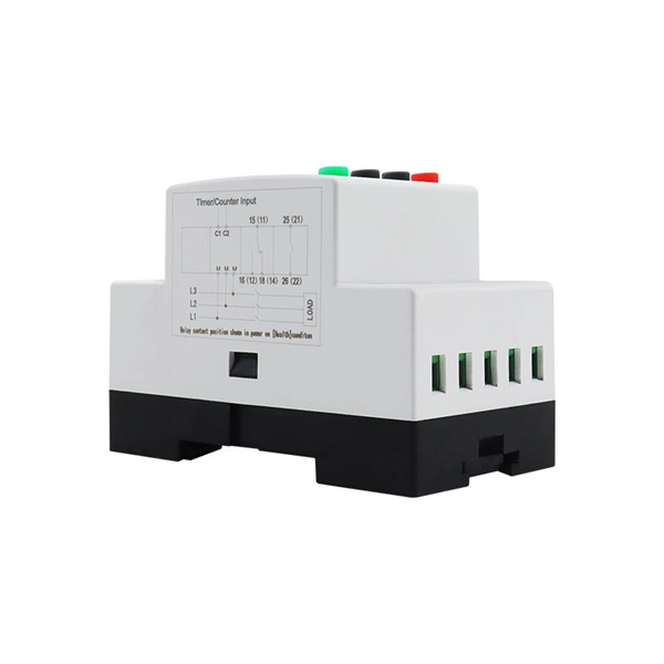
The AC mains high and low voltage cut off circuit I have explained in this article is very easy to build and yet very reliable and accurate. The circuit utilizes a single IC LM 324for the necessary detection and instant.
[PDF]

An MV switchgear cabinet assembly line is a production system designed to streamline the manufacturing process of switchgear cabinets. Each step of the process requires precise control and strict execution to ensure the quality and performance of the final product. Core Function Module Our switchgear production. Switchgear cabinets are divided into high-voltage cabinets and low-voltage cabinets. The. Features: 4. 3 RGV adopts frequency control to make sure of the stable transimission. 4 Assembly line uses module design with flexible deployment. Company's head office, Suzhou Kiande Electric Co., is located in Suzhou. Manufacturing center, Kiande (Zhenjiang) Automation. A complete sets of switch gear production line refers to a modern manufacturing system specifically designed for mass-producing complete sets of switch gear. Complete sets of switch gear production line integrates processes, equipment, personnel, and management systematically to achieve efficient. Kiande, a trusted manufacturer and supplier, is offering wholesale switchgear production lines straight from China. Our production lines are built with the latest technology and adhere to strict quality standards, ensuring efficient and reliable performance. Suitable for power systems, industry and new energy fields, helping upgrade global power.
[PDF]

These regulations may be called Bangladesh Energy Regulatory Commission (Electricity Grid Code) Regulations, 2018 or in short Grid Code. These regulations shall come into force from the date of publication in the official gazette. INTRODUCTION. Title. “Schedule” means the schedule of these Regulations. The Grid Code shall apply in the field of electricity transmission system planning, connection conditions. Bangladesh Energy Regulatory Commission ELECTRICITY GRID CODE 2019 Effective Date: March _ _, 2019 Electricity Grid Code 2019 Bangladesh Energy Regulatory Commission NOTIFICATION Dated: March _ _, 2019 In exercise of the powers conferred by section 59 of the Bangladesh Energy Regulatory Commission. These regulations may be called Bangladesh Energy Regulatory Commission (Electricity Grid Code) Regulations, 2018 or in short Grid Code. INTRODUCTION In exercise. Wherever you are, BANGLAMARK is your reliable partner for the one-stop planning and construction of customized, state-of-the-art high-voltage substations. For power grid operators and utility companies the reliability of their power transmission and distribution equipment installed in their network.
[PDF]
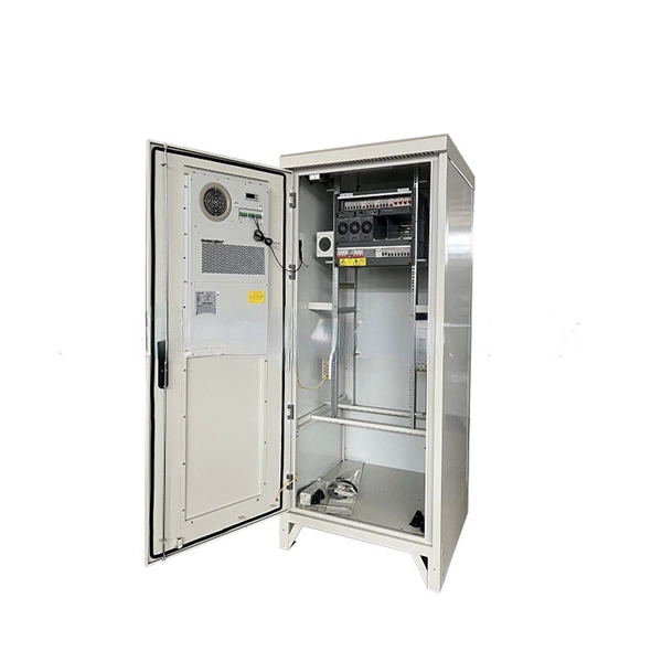
These products are highly integrated, compact in size, structurally compact, safe and reliable in operation, easy to maintain, and portable. In distribution systems, they can be used in ring network distribution systems as well as in dual power supply or radial terminal distribution. High voltage and low voltage complete sets occupy a significant place in modern electrical engineering as they are responsible for safe, secure, and efficient power distribution to all types of industries. They are known as complete switchgear assemblies because they integrate inside them such. Electricity plays a critical role in ensuring national well-being and livelihoods, and the stable development of the power industry drives socio-economic progress. To achieve structural adjustment and transformation in the power industry, the foremost priority is enhancing the performance of. Our high and low voltage complete electrical equipment solutions are designed based on a deep understanding of the current development trends in the power industry and accurate predictions of future power demand. It is mainly used to protect, control and isolate electrical equipment. Its primary functions are to cut off the power supply of equipment to facilitate subsequent maintenance. Senior Electrical Engineer, with 12 years of experience in high and low voltage switchgear installation, commissioning, and overseas project technical support. Currently, Thor is the Technical Department Manager at Weisho Electric Co.
[PDF]

This AutoCAD DWG file includes a complete Single Line Diagram (SLD) of a Distribution Board, showing circuit breakers, wiring connections, and load distribution for lighting, power, and mechanical systems. Knowledge of the basic electrical power distribution system and its components will help the operator understand the importance of electrical power distribution systems. Failure-free power e. Overlapping protective zones a. Protective relays A single, or one-line. A power distribution box (also called PDU or distro) directs electricity from a main source to multiple circuits. It acts like a hub or traffic controller, managing power flow to different areas or devices. Key components include circuit breakers, fuses, bus bars, and internal wiring for safety and. Check electrical parameters: First understand the basic electrical parameters of Distribution box so that you can have a general understanding of the capacity and performance of the distribution box. Analyze the incoming line part: Determine the incoming line source of the distribution box and. ndards and conformity assessment activities in the United States. ANSI facilitates and promotes voluntary consensus standar rty or economic loss due to fire, electrical and related hazards. Now, let's look at how consumers use electrical power. What is a Electrical Power Distribution System? 1. Power supply is received from LT panel and distributed to the outgoing feeders for utilization.
[PDF]

This section provides an overview for optical power meters as well as their applications and principles. Our list of suppliers for that category contains 69 suppliers. Understand the Technical Background To support your technical evaluation, this section includes links to authoritative encyclopedia articles for in-depth verification of the underlying physics, technical issues and techniques. Market Forecast By Type (Thermal Detectors, Photo Detectors), By Instrument/Product Type (Benchtop Meter, Portable Meter, Virtual Meter, Optical Wavelength, Hand-Held Meter, Others), By Detector Type (InGaAs (Indium Gallium Arsenide), Germanium, Silicon, Others), By Power Range (High, Medium, Low). This section provides an overview for optical power meters as well as their applications and principles. Here are the top-ranked optical power meter companies as of May, 2026: 1. Novanta. Photon Systems, Inc. designs, develops, manufactures and markets deep ultraviolet lasers and incoherent sources, instruments based on these sources, and optical and electro-optical accessories for a broad range of applications primarily within the. All of EXFO's modular (IQS line) and benchtop power meters are built for top performance and pinpoint accuracy, and the various models offer a mixture of features and specifications to suit various test setups. Fast, accurate, flexible power. © Copyright© Santec Holdings Corporation.
[PDF]

Optical fibers or fiber cables can be used for transmitting optical power from a source to some application. In their served areas will be power generating stations, alternative energy sources (solar, wind, geotherman, etc. ), substations for distribution and microgrids. These networks must be monitored and managed to ensure reliable power for the utility's customers. For monitoring and managing networks. Low voltage cables are mounted on poles in the "telecom space," well below power cables. Optical power ground wire (OPGW) is an electrical power ground with fiber optics in the center of the conductor. That conversion can be done with a photovoltaic cell. The Commission, on June 22, 1965, noting that the increasing demand for underground electric and communication facilities in California has brought about substantial increases in the construction of such facilities, and that it appeared it may be desirable, pursuant to Sections 761, 768 and 8056 of. One choice is optical power ground wire (OPGW). This conductive cable is run at the top of the tower or pole to be the ground conductor and protect the power cables from lightning. The fiber. While fiber optics is essential for internet service providers to deliver higher bandwidth and faster transmit speeds, there are also many crucial benefits of fiber optics in energy and power. Utility companies face various challenges as they work to deliver reliable energy to homes and industries.
[PDF]

To use a power meter for fiber optic testing, always clean connectors first with lint-free wipes or click-to-clean tools. Select the correct wavelength and set your reference. You measure optical power in dBm or insertion loss in dB. Consistent procedures ensure accuracy. Verify light travels from. The most basic fiber optic measurement is optical power from the end of a fiber. This measurement is the basis for loss measurements as well as the power from a source or presented at a receiver. Typically both transmitters and receivers have receptacles for fiber optic connectors, so measuring the. An optical power meter measures the strength of light traveling through a fiber optic cable, giving you a reading in dBm (decibels relative to one milliwatt). This article will guide you through the methods, instruments, and key considerations for measuring fiber. Fiber optic cabling is the high-performance core of today's datacom networks. As network speeds and bandwidth demands increase, fiber performance requirements have become more stringent. Fiber testing is more important than ever. An OPM uses a photodiode to generate an electrical current proportional to optical power.
[PDF]

Select the correct wavelength and set your reference. You measure optical power in dBm or insertion loss in dB. Consistent procedures ensure accuracy. Measure total signal loss from fiber, connectors, or splices. Optical fiber attenuation is the attenuation per unit length of optical fiber, and the unit is dB/km. When connecting two optical fibers, there will be loss inside any connector or joint. Consistent measurement techniques. While optical power meters are the primary power measurement instrument, optical loss test sets (OLTSs) and optical time domain reflectometers (OTDRs) also measure power in testing loss. TIA standard test FOTP-95 covers the measurement of optical power. Optical power is based on the heating power. Light Source: The CMA5 Series Light Sources provide an economical and stable laser source for use in point-to-point attenuation measurement. They feature a rugged design, built to withstand the difficult testing environment of fiber optic cable installation and maintenance. The CMA5 Light Sources. When talking about optical measurements, wavelength basically means how far a wave pattern repeats itself, usually measured in nanometers (nm). Commonly, a power meter on its own is used to measure absolute.
[PDF]

In this video, we'll show you how to connect an energy meter to a distribution board (DB) safely and efficiently. energy meter connection with distribution box How to Connect an Energy Meter to Your Distribution Box Easily Steps to Properly Connect Your Energy Meter to a Distribution Box. It plays a vital role in ensuring the safe and efficient distribution of electricity throughout the premises. What is the wire from the meter to the breaker box? Also. Always begin with disconnecting the main supply before accessing any enclosure containing distribution components. This prevents arc faults and ensures safety when modifying or inspecting current paths. This “meter to panel” wiring establishes the pathway for all incoming electrical power from the grid to the home. Its primary function is to safely and reliably. Distribution Board aslo know as “Panel Board”, “Switch & Fuse Board” or “Consumer Unit” is a box installed in the building containing on protective devices, such as circuit breaker, fuses, isolator, switches, RCDs and MCBs etc. The electric main supply (230V AC & 120V AC in US) is connected through. Changed Texas's reference diagram for the 3 wire network 120/208 Volt single phase self-contained Revised Figures 13, 14, 14b. Limited the meter location from pad mount transformer for PSO. Removed unistrut being listed as an alternative means for mounting the meter box. APCo and TX do not allow.
[PDF]

We are a one-stop shop for top-notch Electrical Cable Tray in Brazil. Our cable trays are manufactured from robust materials and rigorously tested to ensure they can withstand even the most demanding environments. With 8,500 m² of built area, Eletropoll Trays offers to the market electrical ducts, profiles, beds, accessories, fasteners and support, busbars for lighting and related products. The Tray Unit has achieved excellent certifications. We, one of the top Electrical Cable Tray Manufacturers in Brazil, offer a wide. If you are searching for Cable Tray in Brazil, Brilltech Engineers Pvt. is a trusted brand that you can rely on. We have a well-equipped manufacturing unit with all the advanced resources to cater to your distinct requirements as per your industry preferences. Moreover, our focus on maintaining high quality and. EAE Electric started the production and use of busbar trunking systems in Turkey in the 1970s. Support systems can be manufactured with thicknesses from 2mm to 6mm with Pre-galvanized, Hot Dipped Galvanized, and Painted coatings in various options. EAE cable trays are produced on automatic. Chalfant Ladder Cable Tray Systems are ideal for indoor and outdoor cable management. They provide reliability, ease of installation, and cost savings both initially and long term. With multiple finishes available, we have the perfect ladder tray for any environment. screwless connections.
[PDF]
Temporary power distribution boxes boost efficiency and safety by allowing workers to finish jobs more quickly. They're also durable, making them suitable for frequent transportation and harsh environments.
[PDF]
Incoming power wires must use conduit connections on the bottom plate of the MCC structure to enter the ArcBlok-equipped main circuit breaker unit. A distribution box is the heart of any electrical system. Whether in a home or an industrial facility, this box keeps your electrical setup organized, functional, and efficient. However, the key to. Start by shutting off power at the main disconnect to prevent shock hazards. Remove the panel cover to access internal conductors. Line terminals, typically located at the top of the enclosure, receive incoming service from the utility. These are usually connected to thick black or red wires, each. These boxes full of circuit breakers or fuses distribute incoming power to wiring circuits throughout the house. Top-feed MCC main circuit breaker units with ArcBlok 1200 include a required, 18 in. Commercial line box: Designed for commercial facilities such as office buildings and shopping malls, it has a larger carrying capacity and.
[PDF]