This calculator determines the maximum number of cables that can be safely housed within a cable tray based on its dimensions and the cross-sectional area of the cables. Proper tray and ladder sizing ensures safe, efficient, and maintainable electrical installations in all engineering applications. IEC 61537 and IEC 60364 require evaluating tray dimensions based on cable quantity, type, and layout configuration. Below are industry-standard tray and ladder. A Cable Tray Capacity Calculator is an essential tool for electrical engineers, contractors, and project managers involved in the installation and management of electrical cables. Calculate Cable Cable Calculate the cross-sectional area of a single cable, then multiply by the total number of cables. For mixed cables, sum the areas of all individual cables. Plan cable trays with fill, weight, spacing, and growth checks. Compare standard sizes quickly now. Export clear results for safer electrical layouts and upgrades. The following formula is used to calculate the cable tray capacity: Variables: To calculate the cable tray capacity, multiply the width and height of the cable. This is best exhibited by cable tray width calculations for three different examples of single conductor cables in ladder or ventilated trough cable tray that are permitted by NEC Article 318. The examples are based on installations that contain 12 - 500 kcmil cables (four - three phase - 480 volt.
[PDF]
Parallel connection: A more common method involves connecting capacitors in parallel with the load. This facilitates more adaptability in modifying the capacitance to align with the fluctuating reactive power requirements of the load. Capacitor banks: Multiple capacitors can be grouped together to. Capacitors in parallel are ubiquitous in digital and analog hardware. When used properly, they increase capacitance, reduce unwanted impedance and noise, and improve power integrity across a broad frequency range. Capacitance adds in parallel, increasing total capacitance, since voltage is shared. In the following articles, we will explain the rationale behind connecting capacitor bank in parallel for power factor correction, discuss the consequences of series. Several capacitors can be connected together to be used in a variety of applications. Multiple connections of capacitors behave as a single equivalent capacitor. Walk into any design review where someone is questioning the power delivery network, and within five minutes someone will draw capacitors in parallel on a whiteboard. It's one of the most common configurations in electronics — and also one of the most misunderstood. The formula is dead simple, but. Figure 1: Basic capacitor network configurations showing series and parallel combinations Professional Tip: Always identify series and parallel sections separately before attempting to calculate the overall equivalent capacitance.
[PDF]

A distribution box serves as a central point for managing and distributing fiber optic cables. This device ensures reliable and efficient connectivity between various network components. Cables with and without connectors can be routed, sealed with IP54 (acc. to 60529) and strain relieved in accordance with EN 62444. It is the central electrical supply system of any. In modern electrical systems, cable distribution boxes (also known as electrical distribution boxes or distribution boxes) play a crucial role as the key hub for managing, distributing, and protecting circuits. Whether it is residential buildings, commercial facilities or industrial sites, the. Electrical systems power our homes, offices, and industrial facilities, but behind every reliable electrical setup lies a crucial component that often goes unnoticed: the distribution box. This essential piece of equipment serves as the nerve center of your electrical system, managing power flow. The box is a closed container made of metal or plastic, which contains various electrical components, such as circuit breakers, contactors, relays, etc. They work together to realize the distribution, control and protection of electrical energy. box are usually installed on the walls of buildings.
[PDF]
Choose an SFP module based on the fiber optic cabling that will be connected to the network switches. In addition, fiber cables can transmit data over several kilometers without signal degradation, making them ideal for connecting switches in large campus networks and between different buildings. As they do not emit electromagnetic signals, they're difficult to tap and secure against eavesdropping. Always. I need to connect a single 3750G - 48 ports switch to a single 2960 - 48 ports switch and it needs to be through a fiber. So, PCs connected to one switch would reach the PCs from the other switch. I see that the 3750G switch has (What I believe is) 4 SFP ports and the 2960 has 2 SFP ports. Well, I. In the attached image, AB fiber segment and BC fiber segment are terminated using LIUs. Data Servers are at Location A. One way to inter connect AB and BC segments is by fusing a pair of required fiber cores. But is it. Fiber optic cabling is increasingly used to connect network switches and other datacom equipment, especially in long-distance and mission-critical applications. Fiber provides: Increased internet signal bandwidth. Most modern fiber-enabled network switches require an SFP transceiver module. A fiber optic ring network is a physical or logical network topology where devices (usually switches) are connected in a closed-loop using fiber optic cables. This design ensures data can travel in both directions.
[PDF]
A beam splitter or beamsplitter is an optical device that splits a beam of light into a transmitted and a reflected beam. It is a crucial part of many optical experimental and measurement systems, such as interferometers, also finding widespread application in fibre optic telecommunications. DesignsIn its most common form, a cube, a beam splitter is made from two triangular glass which are glued together at their base using polyester,, or urethane-based adhesives. (Before these synthetic,. Beam splitters are sometimes used to recombine beams of light, as in a. In this case there are two incoming beams, and potentially two outgoing beams. But the amplitudes. For beam splitters with two incoming beams, using a classical, lossless beam splitter with Ea and Eb each incident at one of the inputs, the two output fields Ec and Ed are linearly related to the inputs thro.
[PDF]
A fiber-optic switch allows you to connect two or more fiber-optic cables to form a network. These can behave like a typical Ethernet switch. With a fiber switch combined with a fiber network adapter, you could connect fiber directly to your desktop computer or. Multimode fiber (MMF) is an optical fiber designed to carry multiple light propagation paths—or modes—simultaneously. This is made possible by its relatively large core diameter, typically 50 or 62. 5 microns, compared to the ~9-micron core in single-mode fiber. The wider core accepts light from. Multi-mode optical fiber is a type of optical fiber mostly used for communication over short distances, such as within a building or on a campus. Multi-mode links can be used for data rates up to 800 Gbit/s. Assuming Auto-MDIX is not enabled on these devices, drag the appropriate type of cabling on the left to each connection type on the right. In this blog post, we will discuss the key features and. This article describes the common types of fiber optic cable used for data transmission. Ubiquiti also provides branded optic SFP/SFP+ modules (tranceivers) that are fully compatible with all of our devices. See the page for more information. Back to Top Fiber optic cabling is an alternative to.
[PDF]
Check the electrical load and ensure that the sensors do not exceed the 10 Amp maximum. Check each wire for damage that may lead to a short. Check the tightness of electrical connections along the power supply. Here are some solutions when a power distribution box fails: Safety First: Make sure you are safe. Do not touch live parts, turn off the corresponding power switch to avoid the risk of electric shock. And all the switching and protective devices are installed in the distribution box. Single Phase Distribution Box generally consists of Double Pole MCBs, Single Pole MCBs, and RCCBs. A PDU is a device that distributes electrical power to multiple AV components, such as monitors, projectors, amplifiers, and other equipment in a meeting room. PDUs can vary from basic power strips to sophisticated units with surge protection and monitoring capabilities. Purpose of the Guide: This. A junction box is an important feature of an electrical system as it serves the different connections towards achieving the goal of a proper electrical distribution without leading to short circuits. Material preparation: Prepare the required circuit breakers, wires, wiring ties and other materials, and ensure that they meet the design drawings and installation requirements. Location determination:.
[PDF]
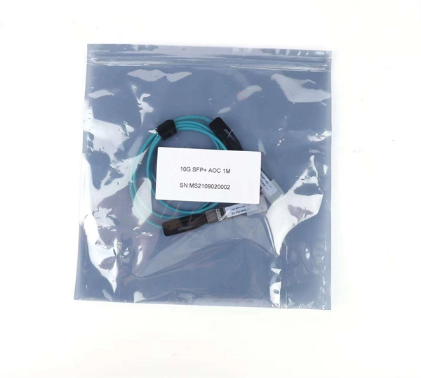
The SFP port is commonly found on Gigabit Ethernet switches and is primarily used for fiber optic device connections or for uplinking 1G switches to aggregation/core layer devices, providing higher-bandwidth links. You can add a compatible SFP transceiver module to the SFP port of. SFP ports enable Gigabit switches to connect to a variety of fiber and Ethernet cables and extend switching functionality throughout the network. Small form-factor pluggable is a hot-swappable interface used to connect network and storage switches and transfer data. Switches with SFP ports can. Choose an SFP module based on the fiber optic cabling that will be connected to the network switches. SFP transceiver modules almost always require two fiber optic cable strands. In this guide, we'll cover the following: What is an SFP port? Why is the SFP port important? SFP vs. QSFP28. Enterprise LANs use the RJ45 port on 100/1000BASE switches. It connects access layer devices and uplinks from desktop switches or directly to end devices. RJ45 ports remain essential for. An SFP switch uses Small Form-Factor Pluggable (SFP) modules to form a network switch for high-speed connectivity between devices. These interchangeable modules support various media types, including copper or fiber-optic cables, providing flexible networking options based on specific requirements.
[PDF]
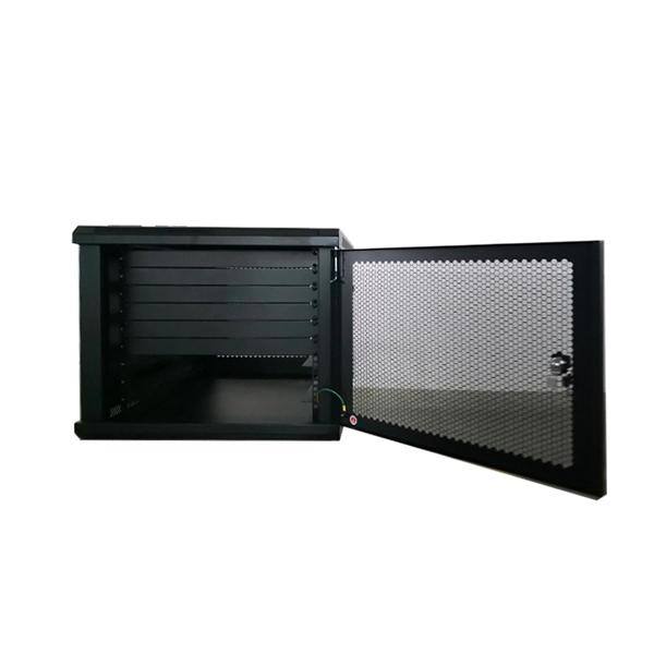
The terminals are where the wires connect to the distribution box. These points ensure a secure and proper electrical connection, allowing the flow of current to pass safely through to the circuits. Connecting a distribution box involves several steps to ensure proper electrical flow. Follow this guide for a clear and safe connection process: Before starting, always ensure the main power is turned off to avoid electrical shock. It helps control and distribute electricity to different areas. Inside, you'll find parts like circuit breakers and fuses that protect the system from problems like overloads and short circuits. Here, a double pole MCB is used as the Main MCB or Main switch. It has the highest capacity than other MCBs used in the DB. Generally, 63A MCB is used as the main switch in most of the domestic. A cable distribution box is an electrical device used to collect, distribute, and protect electrical power. It is mainly used to isolate fault circuits, prevent overload, and ensure the safe operation of. Distribution Box Installation: Put the distribution box on the installation surface, and align the position of the expansion bolts and tighten the screws. Wire. Wire specification: Select the appropriate wire specification according to the circuit load. 5mm² wires, and the air conditioning circuit can use 2. Connection method: Each switch takes a wire from the incoming point and.
[PDF]

Connect the input and output wires to the corresponding terminals of the distribution box. Then press the wire onto the terminal with a wire stripper, or tighten the wire with screws. This step is very crucial and can not bear any faults!. In modern electrical systems, cable distribution boxes (also known as electrical distribution boxes or distribution boxes) play a crucial role as the key hub for managing, distributing, and protecting circuits. Whether it is residential buildings, commercial facilities or industrial sites, the. With the new distribution box, centrally routed cables can be distributed 360° in all desired directions. Cables with and without connectors can be routed, sealed with IP54 (acc. to 60529) and strain relieved in accordance with EN 62444. Always use the right tools when you install coaxial cable. For example, about 0. 01% of. Connecting wires to your home distribution box? See how electricians do it professionally! From selecting the right wire gauge to safely connecting the main. NEC Article 314 establishes requirements for the installation and use of electrical boxes, conduit bodies, fittings, and handhole enclosures. A conduit body is a removable-cover section of a conduit system that provides access at junctions or termination points. Article 314 applies to: These.
[PDF]
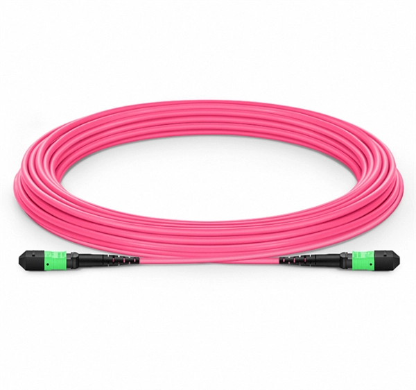
Single mode and multimode fiber optic cables are two different types of fiber optic cable aimed at different use cases. Single mode cables are typically made with a single strand of glass at their core, leading to a n.
[PDF]

Our insulating boxes and electrical material enclosures are available in different sizes and materials, ensuring maximum safety and durability for any type of project. Explore our catalogue and find the best solution for your installations. Painted in gray RAL 7035. It has a quarter turn closure. 2mm thick galvanized steel sheet for mounting the electrical components. Why different prices? Which one is mine? Check rate type We will notify you when it is back in stock. Do. with fuses, 12800 Watt (NL-DE-L). This distribution box has 6 outputs. It is handy and robust. Made of shock-resistant polyamide. 1 x CEE 32A – 5P – 400V. 1. Solid rubber (construction) distribution box suitable for construction and industry according to EN-61439-4. Available from stock. The only one in the Benelux with a Dekra quality mark. Find a huge range of Junction Boxes at Farnell Belgium. We stock a large selection of Junction Boxes, including new and most popular products from the world's top manufacturers including: Hylec, Amphenol Wilcoxon, PRO Elec, V-tac & Multicomp Pro K825. Farnell Belgium offers fast. Enclosures, cabinets, and junction boxes are essential components for housing and safeguarding your electrical connections.
[PDF]

A fiber optic ring network is a physical or logical network topology where devices (usually switches) are connected in a closed-loop using fiber optic cables. Each node is connected to two other nodes, forming a ring-like structure. This design ensures data can travel in both. In this article, we'll explain how to connect multiple Ethernet switches using fiber optic cables and the equipment required for this to work. Network topology refers to the way in which the links and nodes of a network are arranged in relation to each other. If one. Other than entry level network switches, most of today's network switches include one or more GiBC (Gigabit Converter) or SFP (Small Form-factor Pluggable) slots. SFP modules insert into these slots and and require two strands of fiber, typically duplex Using multi mode fiber (for runs under 1000. Fiber optic cabling is increasingly used to connect network switches and other datacom equipment, especially in long-distance and mission-critical applications. Fiber provides: Increased internet signal bandwidth. Most modern fiber-enabled network switches require an SFP transceiver module. Connecting a switch to a fiber optic network involves several steps and requires specific equipment to ensure a successful and efficient connection. Fiber optic technology is widely used in networking due to its high-speed data transmission capabilities and long-distance coverage. This guide will.
[PDF]

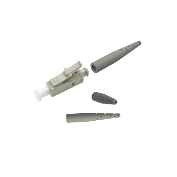
Q1: Can I plug a fiber optic cable directly into an RJ45 port? A: No. They are incompatible. Use a media converter or an SFP-based device. Many people ask the same question: Can you use a fiber optic cable with an RJ45 port? The short answer is no - RJ45 connectors are designed for electrical Ethernet signals, while fiber optics transmit light pulses through glass or plastic. However, modern networks often combine both technologies. Ethernet ports are designed for copper cables (like Cat5e or Cat6), which transmit data using electrical signals. You need a media converter or a. Connecting a switch to a fiber optic network involves several steps and requires specific equipment to ensure a successful and efficient connection. Fiber optic technology is widely used in networking due to its high-speed data transmission capabilities and long-distance coverage. Fiber provides: Increased internet signal bandwidth. Most modern fiber-enabled network switches require an SFP transceiver module. Fiber optic connectors are critical components that facilitate the seamless integration of fiber optic cables with network switches and other networking equipment. These connectors serve as the interface between the delicate optical fibers and the active components of the network infrastructure.
[PDF]
The Fibre Channel physical layer is based on serial connections that use fiber optics to copper between corresponding pluggable modules. The modules may have a single lane, dual lanes or quad lanes that correspond to the SFP, SFP-DD and QSFP form factors. Fibre Channel does not use 8- or 16-lane modules (like CFP8, QSFP-DD, or COBO used in 400GbE) and there are no plans to use these expensive and comple.
[PDF]