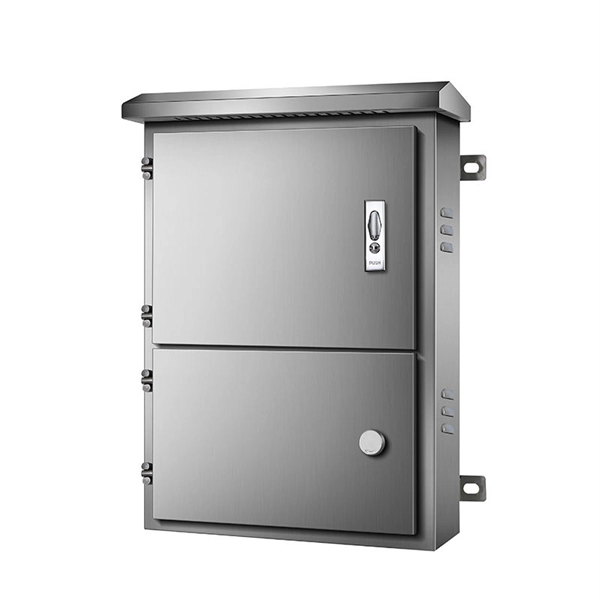
The International Protection (IP) rating system defines minimum requirements for water and dust ingress protection, with outdoor applications typically requiring IP65 or higher ratings. Weatherproof outdoor distribution boxes ensure reliable power distribution in challenging environments by protecting against moisture, dust, and temperature extremes. Key design points include high-quality materials like ABS plastic, aluminum, and stainless steel that resist corrosion and UV. (1) Waterproof distribution box engineered for harsh outdoor and industrial environments, providing IP65–IP68 sealing against dust, rain, and UV. Beyond preventing acute water damage, these enclosures also protect against humidity-related. Yet one factor often overlooked is how well electrical components are protected from dust and moisture. That's where Ingress Protection (IP) ratings come in. If you've ever bought a weatherproof junction box or a distribution enclosure, you've probably noticed codes like IP65, IP67, or IP68 printed. Low voltage distribution box outdoor use requires IP65 or NEMA 4X ratings, corrosion-resistant materials, and proper sealing for lasting weather protection. You use a low voltage distribution box to keep electrical systems safe outside. Let's take a closer look at NEMA ratings and other weatherproofing considerations for.
[PDF]
For steel pipe piles, strain sensing FO cables with steel strands are generally installed on the steel pipe surface using welding and cementation. Then the pile is slowly driven into the soil layer. The installatio.
[PDF]

In this case use an optical power meter (OPM) and test the input port of the splitter for the optical power level (dBm) from the OLT at 1490 nm. If there is no or reduced power then the patchcord or OLT is the culprit. If the power level is reduced it could be as simple as a. So for this simple 1X2 splitter, how do we test it? Simply follow the same directions for a double-ended loss test. Attach a launch reference cable to the test source of the proper wavelength (some splitters are wavelength dependent), calibrate the output of the launch cable with the meter to set. Optical splitters in the outside plant (OSP) are used mostly in passive optical networks (PONs) for fiber-to-the-user (FTTx) networks, and are often overlooked as failure points. In this article I focus on a few basics of optical splitters, their applications, typical causes of failures, and how to. Now, we test the simplest 1x2 optical splitter as the picture shown below. 001 dB), OTDR (for reflection event detection). Cleaning tools. The CertiFiber® Pro Optical Loss Test Set (OLTS) can be used to check that the loss of a PON Splitter (often referred to in various standards as a non-wavelength-selective or wavelength-selective branching device) to check that it is within the allowed defined limits. The CertiFiber® Pro has an.
[PDF]

This report lists the top Passive Optical Network (PON) Equipment companies based on the 2023 & 2024 market share reports. Mordor Intelligence expert advisors conducted extensive research and identified these brands to be the leaders in the Passive Optical . Global Outlook – By Component (Optical Power Splitters, Optical Filters, Wavelength Division Multiplexer/De-Multiplexe), By Structure (Ethernet Passive Optical Networks (EPON), Optical Network Terminal (ONT), Optical Line Terminal (OLT), Gigabit Passive Optical Network (GPON), Optical Network. As per MRFR analysis, the Passive Optical LAN Market Size was estimated at 25555. 89 USD Million in 2024. The Passive Optical LAN industry is projected to grow from 28704. 79 USD Million by 2035, exhibiting a compound annual growth rate (CAGR) of 12. Need. Discover the innovators and market leaders driving Passive Optical Network technology into a new era. Get expert insights into competitive positioning, market trends, and strategic imperatives for stakeholders. For a deep-dive analysis with in-depth forecasts, download the Passive Optical Network. The global passive optical network (PON) market size was valued at USD 17. 80% during the forecast period. 9% from 2024 to 2030. With the proliferation of bandwidth-intensive applications, such as streaming services, online gaming, and.
[PDF]

The fastest way to test a fluorescent tube is with a multimeter set to continuity mode. Each end of the tube has two pins connected by a thin filament inside the glass. If either filament is broken, the tube is dead. The whole test takes about 30 seconds per tube once you know what. This is a complete guide for testing a fluorescent light bulb with a multimeter. You don't have to be an expert in electrical work. This process measures electrical resistance to determine if the tube has suffered an internal failure before replacing the bulb or investigating the ballast. This guide provides a comprehensive understanding of the process, equipping you with the knowledge and. To test a fluorescent light bulb, observe any of the following: flickering light, low brightness, buzzing sound, delayed start, and fading color and light variation. Turn off the power to the circuit that powers the fixture and keep the leads steady to ensure accurate readings. Multimeters provide. How to Test Light Bulbs & Fluorescent Tubes with a Multimeter (Continuity Check) Is your lamp or fixture failing to light up? Before you buy a new bulb, you need to confirm if the bulb or tube itself is the problem! A simple continuity check using a multimeter can instantly tell you if the filament.
[PDF]

This report covers the optical, environmental, and mechanical performance of the LC-UPC, singlemode fiber optic BOAs, provided by Tyco Electronics, Fiber Optics Business Unit. Qualification testing was completed by a third party in July 2004. IDEAL FOR DEBUGGING OPTICAL POWER PERFORMANCE & OPTICAL INSTRUMENT CALIBRATION CORRECION & FIBER SIGNAL ATTENUATION. As optical passive devices, FS attenuators are mainly used in fiber optic to debug optical power performance & optical instrument calibration correction & fiber signal. L-com offers an extensive line of dual wavelength (1310/1550nm) Singlemode fiber optic attenuators. These versatile in-line attenuators are the perfect solution for attenuating Singlemode fiber connectors for both lab and commercial applications. Constructed of the highest quality materials and. zation system's perfo. the power of an optical signal. Our LC/APC single mode attenuators can handle a maximum o 1 watt of optical input power. This device contains one ale and one female LC/APC port. LC/APC optical attenuators can be ordered in attenuation. Fixed loopback type attenuators from OMC offer defined control of optical signals in both integrated and add-on products. Depending on the project or need, fixed attenuators can limit (attenuate) the amount of light passing through to the exact levels your project or application requirement.
[PDF]

Start by examining the plastic cover closely to identify any tabs or locking mechanisms that may be holding it in place. This robust enclosure houses either the main service disconnect or a sub-panel, acting as a control point for electricity distribution to the property or a dedicated outdoor system like a pool or workshop. Gaining access to the panel's interior is usually necessary for simple tasks like resetting a. Opening electrical boxes outside can be a tricky endeavor. Without the proper tools, knowledge, and safety measures, it can also be dangerous. However, with a few simple steps, you can open an outdoor electrical box safely and efficiently. This is how you can open them to have access to the plug-ins. Once you've loosened the. This guide will explore the steps and considerations for safely and effectively punching out a plastic electrical box. Ensure the wires are not powered before starting work. Flat-head screwdriver, electrical pliers, hammer, and a suitable meter or tester. Locate. Before you attempt to open an outdoor breaker box, it's crucial to prioritize your safety. Here is a set of guidelines to ensure you undertake this task without any hazards: Confirm power is disconnected to the unit by turning off the main breaker or disconnecting the main fuse.
[PDF]
A solar meter, also known as a solar irradiance meter or pyranometer, is a device that measures the amount of solar energy or irradiance emitted by the sun. It is commonly used in solar power applications to op.
[PDF]
Fiber testing is the process of verifying the performance of optical fiber cabling. This process includes a range of tests and measurements such as insertion loss, optical return loss, and fiber length. It encompass.
[PDF]
Distance relays, also known as impedance relay, differ in principle from other forms of protection in that their performance is not governed by the magnitude of the current or voltage in the protected circuit but rather on the ratio of these two quantities.OverviewIn, a protective relay is a device designed to trip a when a is detected. The first protective relays were electromagnetic devices, relying on coils operating on moving par. Electromechanical protective relays operate by either, or. Unlike switching type electromechanical with fixed and usually ill-defined operating voltage thresholds.
[PDF]

This guide provides a complete breakdown of enclosure types, materials, certifications, temperature considerations, and installation insights to help engineers, designers, and safety professionals select enclosures that meet both operational and regulatory demands. Explosion-proof enclosures are used by such facilities to ensure the safe housing of electrical components that could cause a spark and ignite these gases in the atmosphere. What Is An Explosion Proof Box or Enclosure? They are a cast aluminum or iron box that can withstand a heavy-duty explosion. Explosion-proof and flameproof equipment is essential for safe operation in hazardous (classified) locations where flammable gases, vapors, or combustible dusts may be present. What Are Hazardous Area. Pepperl+Fuchs provides a specialized portfolio of Ex d (flameproof) and Ex tb (dust protection by enclosure) certified terminal boxes and junction boxes engineered for reliable use in explosion-hazardous areas. These sturdy solutions are certified according to global standards such as ATEX, IECEx. Blast-proof enclosures are protective devices designed to prevent the consequences of fires & explosions. Such structures are specially configured to be pressure vessels hence they can contain internal pressure without propagating it. Rather than stopping an explosion from occurring, the equipment safely manages it within a reinforced structure. Common protection methods include: These principles are.
[PDF]

The National Electrical Code (NEC) has established eight levels of fire resistance for fiber optic cables. These levels are based on the time it takes for a cable to burn through or melt. Corning Optical Communications manufactures quality flame retardant optical fiber cables for indoor applications, which comply with the requirements of the National Electric Code® (NEC® 2023) published by the National Fire Protection Agency (NFPA). To ensure compliance to these requirements, a. Understanding the listing requirements of fire alarm circuit cables can help you make sense of the cable alphabet soup. Here are some highlights from Part IV of Article 770. There's plenty of "expansion room" built into Article 770. Part I ends with Section 770. 44. Cabling Installation & Maintenance - Classes 1, 2, 3, and 4, communications, fire alarm, and optical fiber cables are all addressed in the NEC. By Stanley Kaufman, PhD, CableSafe Inc. UL Solutions' long-standing history in certification and Standards development makes us a trusted thought leader in the. Understanding the fire ratings and jacket options for fiber optic cables is crucial for ensuring optimal performance and safety. This technical guide will provide a comprehensive overview of these factors, their implications on cable resilience and transmission, and tips for making informed.
[PDF]

Towers are not rooted by only pouring concrete—they require extensive soil analysis, wind loads, types of towers, and seismic activity to determine the necessary foundation for safety and sustainable use. A communication tower foundation design is the structural blueprint that determines the anchor point of the tower on the ground. This article delves into the intricate process of civil construction tailored. Tower owners must comply with a multi-layered regulatory, engineering, and safety framework that governs tower siting, where a cell tower can be built, how it must be designed, and how it operates throughout its lifecycle. These requirements ensure public safety, structural integrity, regulatory. Here are six foundation types for communication towers that work for a wide range of situations and environments. If you're planning a new installation, knowing the basics of these foundations can help you establish a secure and durable tower that will be a community asset for years to come. Telecom (Telecommunications) towers are a generic description of radio masts and towers built primarily to hold telecommunications antennas. As such antennas often have a large area and must be precisely pointed out, such towers have to be designed and built to limit wind induced movement. The Contractor shall employ a quality control program that will ensure that engineering, fabrication.
[PDF]

For renewable energy applications, specifically in wind and solar power plants, the IEEE C37. 232 standard specifies the requirements for relay protection of these systems. For those not familiar with the different elements that form a WEP, commonly known as a Wind Farm, this report introduces a description of the different elements comprising a wind farm and how their unique characteristics may be considered to provide a proper design. For successful application of. Abstract—A wind electric plant (WEP) is made of many wind turbine generators spread over a large area and includes many subsystems that need to be protected. It is important to ensure that all the subsystems are well protected and coordinated to maximize the reliability (security and dependability). Protection of Wind Electric Plants is a report covering engineering considerations for the design of protection systems and present relay protection and coordination practices at wind electric plants. The report includes protection of generator step up transformers, collector system feeders. In this paper, the performance of classical protection functions of two commercial relays (denoted as A and B) are investigated. The relays are tested in a Hardware-In-the-Loop environment and the strengths and weaknesses of these functions are determined. These specialized switches serve as crucial safety mechanisms that isolate circuits.
[PDF]

It includes first determining the type of communication system (s) which will be carried over the network, the geographic layout (premises, campus, outside plant (OSP, etc. ), the transmission equipment required and the fiber network over which it will operate. Fiber optic network design refers to the specialized processes leading to a successful installation and operation of a fiber optic network. It also involves selecting transmission equipment. It includes detailed mapping of backbone, distribution, and drop connections for FTTH, FTTP, FTTx, and enterprise networks. Building a fiber optic network is a highly technical yet vital process that enables communities and businesses to access high-speed, reliable fiber optic internet. From the initial site survey to the final fiber to the home (FTTH) connection, every stage requires careful planning, coordination, and. Designing a fiber optic network is like planning a city's road system, it needs to be efficient, reliable, and built to handle both current and future traffic. Whether you're new.
[PDF]