
5 dB depending on splitter type. Common planning value: 0. Optional: patch panels, attenuators, or extra components. Helps cover dirt, aging, and measurement tolerances. Adds Rx power and margin calculation. Calculate insertion loss for passive optical splitters in PON and distribution networks. Power is divided equally among output ports. Excess loss accounts for manufacturing imperfections, typically 0. DISCLAIMER: These calculators are provided for. Optical splitters, encompassing FBT (Fused Biconical Taper) couplers and PLC (Planar Lightwave Circuit) splitters, are prevalent passive optical devices designed to divide fiber optic light into multiple segments based on a specified ratio. Fiber optic splitters are vital components within. In fiber optic networks, particularly in FTTx (Fiber to the x) and PON (Passive Optical Networks) deployments, splitters play a central role in distributing the optical signal from a single source to multiple destinations. Optional: patch. Understanding optical splitter loss isn't just about plugging numbers into a calculator. It's about knowing what factors contribute to that loss, how manufacturers specify it, and how it impacts the overall performance and reach of your network. Understanding the types of splitters, their impact on network performance, and how to measure their losses ensures high-quality network operation and facilitates optimal splitter selection based on.
[PDF]

5 dB depending on splitter type. Common planning value: 0. Optional: patch panels, attenuators, or extra components. Helps cover dirt, aging, and measurement tolerances. Adds Rx power and margin calculation. Use 2×N when two inputs feed the same distribution stage. Wavelength is recorded in outputs for documentation. Optional: patch. FTTH / PON Splitter Loss Calculator - Zion Communication is a professional manufacturer of cables and accessories for signal and low voltage transmission. Estimate whether an FTTH or PON optical link is feasible by calculating PLC splitter loss, fiber attenuation, connector loss, splice loss and. In fiber optic networks, particularly in FTTx (Fiber to the x) and PON (Passive Optical Networks) deployments, splitters play a central role in distributing the optical signal from a single source to multiple destinations. These are known as passive optical splitters, and they perform the function. The formula for the theoretical loss for each output port of a splitter with N output ports is: Theoretical Split Loss (in dB) = 10 * log10 (N) Where: N is the number of output ports the splitter has (e., 2 for a 1x2 splitter, 4 for a 1x4, 8 for a 1x8, 32 for a 1x32, etc. Passive split links usually lose the most dB at the splitter, so we keep the optical budget and the installed route separate. These are especially important for FTTH (Fiber to the Home), data centers, and Passive Optical Networks (PON), where.
[PDF]

Attenuation describes the continuous loss along the fiber, while insertion loss describes the additional loss caused by components such as connectors, splices, or splitters. In fiber optic networks, particularly in FTTx (Fiber to the x) and PON (Passive Optical Networks) deployments, splitters play a central role in distributing the optical signal from a single source to multiple destinations. The split ratio and insertion loss are two key parameters defining their performance. A deeper understanding of these. This document describes how to calculate the maximum attenuation for an optical fiber. You can apply this methodology to all types of optical fibers in order to estimate the maximum distance that optical systems use. There are no specific requirements for this document. This document is not. By dividing a single optical signal from a central Optical Line Terminal (OLT) into multiple outputs for Optical Network Terminals (ONTs) at users' homes, splitters eliminate the need for dedicated fibers to each residence—slashing infrastructure costs while scaling network reach. Losses can be introduced by various means such as intrinsic material absorption, scattering, bending, connector loss and more. The tutorial has the following parts: When light propagates as a guided wave in a fiber core, it experiences some power losses. These are particularly important for long-haul data transmission through fiber-optic telecom.
[PDF]

In this case use an optical power meter (OPM) and test the input port of the splitter for the optical power level (dBm) from the OLT at 1490 nm. If there is no or reduced power then the patchcord or OLT is the culprit. If the power level is reduced it could be as simple as a. So for this simple 1X2 splitter, how do we test it? Simply follow the same directions for a double-ended loss test. Attach a launch reference cable to the test source of the proper wavelength (some splitters are wavelength dependent), calibrate the output of the launch cable with the meter to set. Optical splitters in the outside plant (OSP) are used mostly in passive optical networks (PONs) for fiber-to-the-user (FTTx) networks, and are often overlooked as failure points. In this article I focus on a few basics of optical splitters, their applications, typical causes of failures, and how to. Now, we test the simplest 1x2 optical splitter as the picture shown below. 001 dB), OTDR (for reflection event detection). Cleaning tools. The CertiFiber® Pro Optical Loss Test Set (OLTS) can be used to check that the loss of a PON Splitter (often referred to in various standards as a non-wavelength-selective or wavelength-selective branching device) to check that it is within the allowed defined limits. The CertiFiber® Pro has an.
[PDF]
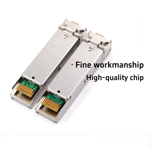
PLC Splitters are based on planar waveguide circuit technology. Inside the splitter, a silica glass substrate routes the incoming optical signal through a waveguide and evenly splits the light into the desired number of outputs. Planar Lightwave Circuit (PLC) Splitter is a type of passive optical component using silica optical waveguide technology to distribute optical signals from the Central Office (CO) to multiple premise locations, allowing for efficient communication. FS Bare Fiber Splitters are engineered for. It is widely used in passive optical networks to realize optical signal power splitting with 1xN or 2xN splitting ratio. Gigalight provides a series of customized PLC splitters to meet different Length, Output Fiber Type, Output Fiber Length, Input connector, and Output Connector etc. All. PLC optical splitters (planar waveguide optical splitter) is a key component in optical fiber communication networks and is widely used in optical fiber distribution systems such as FTTH (fiber to the home) and PON (passive optical network). They are fabricated with silica optical waveguide technology; maintain superior channel-to-channel uniformity and stability through a wide ange of environmental and mechanical conditions. All optical fibers used in Wirewerks PLC splitters are bend.
[PDF]
The answer is yes, and it's a practice widely used in the industry to distribute signals to multiple destinations without degrading the signal quality significantly. This article delves into the methods, benefits, challenges, and practical applications of splitting fiber lines. A fiber optic splitter is a passive optical component that divides a single incoming optical signal into two or more outgoing signals, or combines multiple incoming signals into one. Its primary role is in Passive Optical Networks (PON), which are the foundation of. Fiber splitters are critical in optical networking, skillfully dividing a single light signal into multiple outputs for diverse applications. Their passive operation allows for widespread use in telecommunications, data distribution, and sensor systems, making them a backbone technology in. Power splitters (also commonly called “optical splitters”) are devices that divide an optical signal into multiple, equal-intensity output signals. The split ratios are usually even, like 1:2, 1:4, 1:8, and up to 1:32. Other split ratios are available, but usually come at a higher cost as they have. An optical splitter is a passive bidirectional element, which is used to connect a large number of subscribers/ONUs to an OLT. It is one of the most important elements of all FTTx PON and OLAN networks. What is Fiber Line.
[PDF]
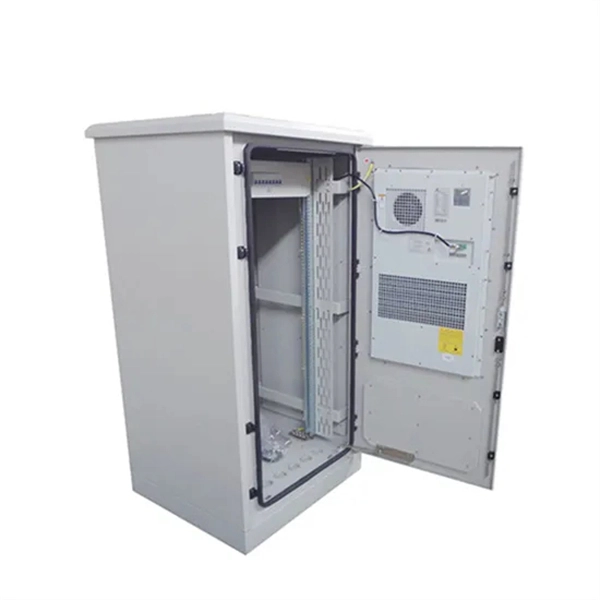
A splitter terminal box serves as a specialized enclosure that manages, splices, and distributes fiber optic cables within modern networks. In modern FTTH (Fiber to the Home) and optical communication networks, three types of fiber distribution products are widely used: Splitter Distribution Box, ODF (Optical Distribution Frame), and Fiber Terminal Box. Although they all belong to the optical distribution and management system, their. A fiber optic splitter is a passive optical component that divides a single incoming optical signal into two or more outgoing signals, or combines multiple incoming signals into one. It is. many aspects of a Fiber to the X (FTTx) network. Splitter architectures can impact fiber counts, splicing needed, numbers of fiber needed, and the customer on-boarding process. conversations and confusion in the industry. of splitting architectures. A “splitter” is a power splitter. A splitter is. This guide will demystify this pivotal passive device, exploring its types, working principles, and how it seamlessly integrates with optical transceivers to bring high-speed internet to your doorstep. 📄 What is an Optical Splitter? An Optical Splitter, also known as a beam splitter, is a passive.
[PDF]
An optical coupler helps split or join light signals in a fiber network. It can take one light signal and send it to two or more places. They do not send signals to the. An Optical Splitter, also known as a beam splitter, is a passive optical device that divides a single input optical signal into two or more output signals. Unlike active devices (which require power), splitters operate without electricity, relying solely on the physics of. You use optical couplers and splitters to split or join signals in fiber networks. For example, optical splitters send light to many output ports. This lets you connect more users to one network terminal. You can also use them to join light from. Optical Distribution Network (ODN) - The physical fibre and optical devices that distribute signals to users in a telecommunications network. The ODN is composed of passive optical components (POS), such as optical fibers, and one or more passive optical splitters. Optical Network Termination (ONT). Functioning as a translator, the ONT converts optical signals from the fiber optic cable into electrical signals that your router and devices can understand. In essence, it serves as the bridge between your internet service provider's (ISP) network and your home network. This type of device plays an important role in passive.
[PDF]

Fiber optic loss calculation formula: Total link loss (LL) = Cable attenuation + Connector attenuation + Fusion attenuation [Note: If there are other components (such as attenuators), their attenuation values can be added]. Intrinsic Optical Fiber Losses comprise of absorption loss, dispersion loss and scattering loss caused by the structural defects. The detailed information about these optical losses and how to reduce them are. Calculate fiber optic signal loss based on cable length, attenuation, and connector losses. Determine cable loss, connector loss, and total system loss in decibels (dB) to assess signal quality and repeater requirements. Fiber optic loss is calculated in two parts: cable loss and connector loss. This calculator determines fiber loss based on input power, output power, and the length of the fiber optic cable. In summary, fiber optic loss is. Use this worksheet to input values for all variables that will impact your system's performance. After entering your values, please ensure you click the 'Calculate Link Loss' button at the bottom of the page to generate your total link loss. This step is necessary to see if your system falls within. Optical fiber loss is a term for signal loss affecting transmission reliability. Optical fiber loss is.
[PDF]

A fiber-optic splitter, also known as a beam splitter, is based on a quartz substrate of an integrated waveguide optical power distribution device, similar to a coaxial cable transmission system. The optical network system uses an optical signal coupled to the branch distribution. The fiber optic. In the backbone of modern Fiber-to-the-Home (FTTH) networks, optical splitters serve as the unsung heroes that enable cost-efficient connectivity for millions of subscribers. By dividing a single optical signal from a central Optical Line Terminal (OLT) into multiple outputs for Optical Network. Optical splitter, also called optical beam splitter, is an integrated waveguide optical power distribution device that can split an input optical signal into two or more output optical signals, and the optical input power is evenly distributed on all output ports. For example, an optical splitter. The answer lies in a small device. We call it an Optical Splitter. This device is the heart of Passive Optical Networks (PON). It allows service providers to save money. It helps them distribute bandwidth efficiently. In this article, we explain the definition, working principles, types, and. An optical splitter is a device that divides light transmission in a network into multiple output ends. It plays a crucial role in facilitating network interconnections.
[PDF]
The main trade show for the large optical module industry is the Optical Fiber Conference (OFC), that is held annually in southern California. Other prominent shows for the industry include ECOC in Europe and FOE in Japan.
[PDF]
An optical time-domain reflectometer (OTDR) is an optoelectronic instrument used to characterize an optical fiber. It is the optical equivalent of an electronic time domain reflectometer which measures the impedance of the cable or transmission line under test. An OTDR injects a series of optical pulses into the fiber under test and extracts, from the same end of the fiber, light that is scatter. Reliability and quality of OTDR equipmentThe reliability and quality of an OTDR is based on its accuracy, measurement range, ability to resolve and. The common types of OTDR-like test equipment are: 1. Full-feature OTDR: 2. Hand-held OTDR and Fiber break locator: 3. RTU in RFTSs:. In the late 1990s, OTDR industry representatives and the OTDR user community developed a unique data format to store and analyze OTDR fiber data. This data was based on the specifications in GR-196, G.
[PDF]
Please select a category, brand, and model to find a type-approved device. Results will be displayed here after search. You can now apply and manage your RSB services online. Start today! The RSB Standards Store has a wide range of Standards covering various sectors and industries. Need help with any of your other applications? Apply for Zamukana Ubuziranenge and get assistance from our staff. Increase the. An LPO (Linear Pluggable Optics) solution offers considerable power savings for optical interconnect by removing the digital signal processing (DSP) function from the pluggable optical module. The idea is simple: instead of a DSP (digital signal processor) inside the module – replacing it with transimpedance amplifier (TIA) and a driver chip with high linearity and EQ capability – LPO shifts signal processing into. LPO (Linear-drive Pluggable Optics) is a transceiver packaging technology. It utilizes specialized components, including ASIC substrates, ASIC. In response, several solutions such as Linear Receive Optics (LRO), Linear Pluggable Optics (LPO) and Co-Packaged Optics (CPO) have been proposed. 1 shows the typical block diagram of a pluggable transceiver consisting of on-board lasers, optics, a Photonics die housing the modulator.
[PDF]
Connectorized attenuators often have a quite compact housing, essentially looking like a fiber-optic adapter. Some of these devices provide a fixed level of attenuation, quantified as the insertion loss in decibels. An optical attenuator, or fiber optic attenuator, is a device used to reduce the power level of an optical signal, either in free space or in an optical fiber. The basic types of optical attenuators are fixed, step-wise variable, and continuously variable. Optical attenuators are commonly used in. Fiber-optic attenuators are a specific type of optical attenuators which are used in fiber optics, e. for achieving a suitable signal level for a data receiver in a telecom system. It primarily ensures the power or amplitude of a signal is lowered without significantly distorting its waveform. The attenuator circuit will allow a known source of power to be reduced by a predetermined factor, which is usually expressed as decibels.
[PDF]

Convenient Supply Solutions for Oscilloscope Probes Products for resellers and dealers based in Uzbekistan serving Tashkent, Namangan, Samarkand, Andijan, Bukhara, Nukus, Qarshi, Kokand, Chirchiq, Fergana and more. Lenses made from all optical glasses, including Si, CaF2, Ge, ZnSe, ZnS, quartz, and sapphire: Standard lenses in all common designs as well. Optical surface inspection detects minimal defects. This way, you produce your workpieces with consistently high quality. com is a proven supplier of Oscilloscope Probes products dealing major product. According to Volza's Optical,Instrument Import analytics, 698 verified Optical,Instrument buyers in Uzbekistan have imported Shipments from 661 global suppliers. OOO HILBRO accounted for 51% of Uzbekistan's total imports with (1,143 shipments). IP OOO. Compare products based on your own technical specification criteria. How does our search work? With MEET OPTICS search you get direct access to our database of thousands of optical components from providers worldwide. Prices and product specifications directly listed from optical component. Copyright © 2022 GOC-UZ. See our terms of use and privacy policy. Find and discover Optical Equipment buyers & importers for all products in Uzbekistan, featuring details on their shipment activities, trade volumes, trading partners, and more. Subscribe to global trade data intelligence to.
[PDF]


