
How to Use Optical Power Meter TR-504 | Optical Power Meter Working| Testing OPM, VFL, RJ45 | TRICOM In this video, we walk you through how to use the TRICOM TR-504 Optical Power Meter and explain how it works. Learn how to test fiber optic cables, OPM, VFL . Optical power meters are a key element in the optimization and maintenance of such optical networks and of their components. In this article, learn: What is an optical power meter? An optical power meter (OPM) measures the power levels of light signals in devices that transmit data or power using. An optical power meter measures the strength of light traveling through a fiber optic cable, giving you a reading in dBm (decibels relative to one milliwatt). The basic process is straightforward: turn the meter on, set it to the correct wavelength, clean your connectors, plug in, and read the. OPM interface: insert the fiber to be tested, test the optical power. An optical power meter is a tool that measures the number of optical power in a cable is fiber-optic. It helps engineers verify the performance of optical fiber systems, ensuring that the signal strength meets requirements, and is an essential tool for communication network maintenance and troubleshooting.
[PDF]

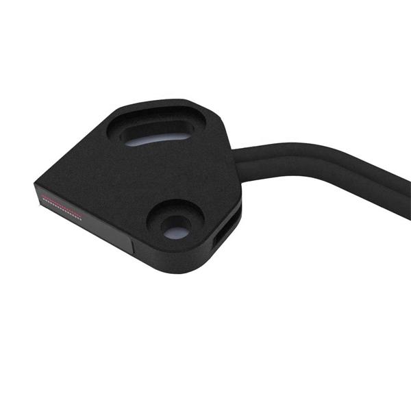
It consists of 5 buttons. A power button, a button to turn on the VFL, a lambda button to set the wavelendth, a REF button, and a dBm/W button to set the unit of power. First, you check the initial power of a light signal. Then you check its power at the other end of optical. OPM interface: insert the fiber to be tested, test the optical power. REF/dB key: Short press the dB to switch unit, click once nW/dBm/dB to enter the upper clear data, press and hold until REF is displayed on the screen, and set the current optical power as reference value, enter the relative. There are two buttons on this meter. One is the power button, used to turn the meter on/off. At the top, there is a sensor that detects the light beam. The. at -22 (or 25 with tone on)). To do this you. Active Equipment Power Measurement Fiber Continuity Patch Cable Testing Check MM Reference Cables - Dual OWL MM Sources Check MM Reference Cables - WaveSource MM Sources Check SM Reference Cables - Laser OWL SM Sources Check SM Reference Cables - WaveSource SM Sources. Power-off: Press and hold “MODE” key for 2 seconds or more until “OFF” displays on the screen. Note: This instrument will shut down automatically without receiving any operation instruction for 10 minutes. Function selections: It.
[PDF]

Here's a list of the best Routers for Enterprise. Filter the results based on user ratings, pricing, features, platform, region, support, and other criteria to find the best option for you. 1. Full-service routers designed to serve as enterprise WAN core nodes, large enterprise network access nodes, DCI nodes, and campus or large-scale IDC network egress. Optical networking equipment includes fiber optic cables, transceivers, switches, and routers. The market is driven by the. Our Engineers take a hands-on approach to replicating networks, maintaining reliability and providing the highest level of service. Wi-Fi 6 (802. 11ax) indoor wireless access point Dual-radio, dual-band Up to. Desktop All-in-One enterprise-class wireless router Including 5 Gigabit ethernet ports. Reyee 10-Port Gigabit Cloud Managed Router 10-Port Gigabit Cloud Managed. Reyee 10-Port Gigabit Cloud Managed PoE Router 10-Port. Future-proof your network with our full-stack offer. Get started with the right security solution for you. See more, move faster, go farther. Human. To provide secure, reliable affordable and high quality converged telecommunication services anytime, anywhere for an accelerated inclusive socio-economic development. To develop a robust and secure state-of-the-art telecommunication network providing seamless coverage with special focus on rural.
[PDF]
Run the display device command to check the switch model. Log in to com/onlinetoolsweb/lpcmmt/en/index. html to view the optical module types supported by the switch. If you know the model or type of an optical module, you can view the section "Pluggable Modules for Interfaces" in the Hardware Description to look up parameters of the optical module, including the center wavelength, transmission distance, fiber types supported, receive optical power, and transmit. Taking the Huawei 5700 series switches as an example, the commands to view optical module information are as follows: Transceiver Type :1000_BASE_SX_SFP Connector Type :LC Wavelength(nm) :850 Transfer Distance(m) :300(50um),150(62. 5um) Digital Diagnostic Monitoring :YES Vendor Name. The following uses the Moduletek SFP-10G-LR module connected to a Huawei S6700 switch as an example to introduce how to read information of the connected optical module on a Huawei switch. Run the display transceiver [interface interface-type interface-number | slot slot-id] , to view the information on. Here are the common commands to use to display hardware-related information on Huawei Routers. The inventory information such as serial number, product code,optical module,device, power,voltage,temperature,fan, CPU and memory are very important on operation and troubleshooting purposes. The specific viewing information is as follows:.
[PDF]

This standard covers the construction, mechanical, electrical, and optical performance, installation guidelines, acceptance criteria, test requirements, environmental considerations, and accessories for a nonmetallic, all-dielectric self-supporting (ADSS) fiber optic cable. An All-Dielectric Self-Supporting (ADSS) cable operates without metallic messengers, relying entirely on its aramid yarn strength members. For a typical 12-fiber ADSS cable with a 8. AFL-ADSS® (All-Dielectric Self-Supporting) cable is ideal for installation in distribution as well as transmission environments. This guide provides general recommendations for the selection of methods, equipment, and tools for the stringing of ADSS (All Dielectric Self-upporting) fiber optic cables including short and Long Span ADSS cables. The installation methods for ADSS cables are essentially the same as those used for. This Installation Manual is a recommendatory installation document provided by HANGZHOU ZION COMMUNICATION CO. The installation manual is established based on the newest issued international standards such as lEEE Std 1222: 2004, "lEEE standard for all-dielectric. Round aramid reinforced ADSS cable for intermediate and long spans, 4 – 96 fibres. VDE: A- DF 2Y (ZN) 2Y This specification covers a family of optical cables with 4 - 96 fibres for intermediate and long spans.
[PDF]
This OPT-110 cable from Hosa is designed to interconnect digital audio components with Toslink jacks and is compatible with ADAT and all S/PDIF formats, including Dolby Digital and DTS surround. All Hosa cables purchased in the USA come with a lifetime warranty. Hosa cables are exceedingly popular, due in part to their reputation as being one of the most affordable and high-quality cable lines in the business. Read more You save 27%! Item usually available to ship in 9-12 Business Days. Please call for up-to-date information on product availability. Deciding to equip your venue with a live sound system requires much forethought, planning and a unique design tailored to your space and the type of sound that will be amplified there. Let the experts at Pro Audio Solutions help outfit your space with the appropriate and best quality professional. Added to your Order Confirmation, Invoice, and Dispatch note for this order only. Buy OPT-110 - HOSA - FIBER OPTIC CABLE, TOSLINK TO SAME, 10 FT. Newark Electronics offers fast quotes, same day dispatch, fast delivery, wide inventory, datasheets & technical support. Add Aeris Protective Packaging for $9. 99, a $37 value What's This? 1-day Delivery for Most PA and FL orders! No Tax Outside CA, FL and PA! Shipping Note: Due to size and/or weight specifications, there is an additional shipping fee of that will be added during checkout. Shipping Note: Due to limited.
[PDF]

Key finding: This paper develops analytical models and design procedures of ultra-wideband Wilkinson power dividers using linearly tapered transmission lines (TTLs) which provide size reduction and broadband performance. Read more. Power dividers are the passive electronic equipment used for splitting the power. They are now being employed in a variety of communications applications such as telephonic, antennas configurations, mobile connectivity, internet technology, & optics, etc. They come up with very low loss, operate at. RF and microwave power splitters and dividers create two copies of the same signal, while ideally preventing crosstalk between the outputs. Doing this with minimal loss while maintaining signal integrity is a challenge. In this article we explain how power splitters work and what the tradeoffs are. The rise of wireless connectivity requirements for applications such as Internet of Things (IoT), cellular, and automotive electronics is resulting in systems that are increasingly using RF signals, components, and subsystems. Often, designers need to direct these signals to more than a single. A power divider is a passive electronic device used in radio frequency (RF) and microwave applications to split an input signal into multiple output signals with equal or specified power levels, while maintaining impedance matching to minimize signal reflection and loss. How can power dividers.
[PDF]

A good laser source for a singlemode link will have a power output of ~ +3 to +6 dBm - 2-4mw - coupled into the fiber. Tx power (transmission power) refers to the intensity of the optical signal output by the transmitting end of the optical module. However, in practical use, we adopt the average Tx power. These modules, including SFP, SFP+, and SFP28, are widely used in enterprise networks, data centers, and carrier-grade deployments. Optical loss is measured in “dB” which is a relative measurement, while absolute optical power is measured in “dBm,” which is dB relative to 1mw optical power Loss is a negative number (like –3. 2 dB) while power measurements can be either positive (greater than the reference) or negative (less than. SFP (Small Form-Factor Pluggable) modules are compact transceivers that allow for high-speed communication between network devices. They are essential in applications like telecommunications, data centers, and enterprise networks. Generally, the power levels are specified in terms of transmit (TX) power and. Transmit power is the power at which the transmitter of an optical transceiver module transmits optical signals in dBm. When the signal received is outside of the range, there is a.
[PDF]

Learn how to monitor SFP optical power on Cisco switches, interpret Tx/Rx levels, and troubleshoot fiber link issues. Step-by-step CLI commands, model-specific guidance, and best practices included. In this article, we will break down the key factors influencing TX/RX power, explain how to calculate the optical power budget, and provide actionable insights for optimizing your network's performance using SFP modules. SFP (Small Form-Factor Pluggable) modules are compact transceivers that allow. SFP (Small Form-factor Pluggable) optical modules are compact, hot-pluggable transceivers that enable network equipment to connect seamlessly to fiber and copper links. Even if an interface appears up, degraded Tx/Rx levels can cause intermittent flapping, packet loss, or err-disabled states. Think of it as the “translator” for your network equipment, converting electrical signals into optical signals. The most two important factors of the SFP transceiver: Output power (TX power) and receiver sensitivity (RX sensitivity). The optical TX power is the signal level leaving from that device, which should be within the transmitter power range. The RX sensitivity is the incoming signal level being. In current network communication, SFP optical modules are an indispensable physical foundation for building network channels. They form high-speed channels for optical signal transmission. Therefore, to ensure their.
[PDF]

In this video, we'll show you how to connect an energy meter to a distribution board (DB) safely and efficiently. energy meter connection with distribution box How to Connect an Energy Meter to Your Distribution Box Easily Steps to Properly Connect Your Energy Meter to a Distribution Box. It plays a vital role in ensuring the safe and efficient distribution of electricity throughout the premises. What is the wire from the meter to the breaker box? Also. Always begin with disconnecting the main supply before accessing any enclosure containing distribution components. This prevents arc faults and ensures safety when modifying or inspecting current paths. This “meter to panel” wiring establishes the pathway for all incoming electrical power from the grid to the home. Its primary function is to safely and reliably. Distribution Board aslo know as “Panel Board”, “Switch & Fuse Board” or “Consumer Unit” is a box installed in the building containing on protective devices, such as circuit breaker, fuses, isolator, switches, RCDs and MCBs etc. The electric main supply (230V AC & 120V AC in US) is connected through. Changed Texas's reference diagram for the 3 wire network 120/208 Volt single phase self-contained Revised Figures 13, 14, 14b. Limited the meter location from pad mount transformer for PSO. Removed unistrut being listed as an alternative means for mounting the meter box. APCo and TX do not allow.
[PDF]

The operation and skills of fiber optic fusion splicing technology can be mainly divided into five steps: fiber stripping, fiber cutting, fiber melting, fiber sleeve, and fiber winding. Two types of splices are used in fiber optic cabling one is Mechanical the other is Fusion. And tools used for fiber fusion: fusion splicer; fiber cleaver; cable stripper; fiber optic stripper; alcohol;. These specialized devices are engineered to manipulate, terminate, join, and verify light-carrying strands without introducing microscopic fractures or contamination. At Weunion, we categorize these essential instruments into four primary operational phases: Preparation: Removing protective layers. Various techniques can remove the coating: Regardless of the method used to strip the coating, it is important to use the correct tools and techniques to prevent damage to the bare glass. Ensuring the fiber. What is Fiber Optic Splicing and Why is it Needed? – #1. Use and Maintain Your Cleaver Correctly – #3. Set Your Fusion Parameters in a Systematic Way What is Fiber Optic Splicing and Why is it Needed? First, let us understand the meaning of the term. Fusion splicing joins two optical fibres end-to-end using heat, creating a seamless connection for minimal signal loss. owever, proper cable preparation is essential before firing up your fusion splicer. A poorly prepared fibre can lead to weak splices, high attenuation, or complete failure.
[PDF]
Explore 20 top manufacturers and suppliers of Optical Time-Domain Reflectometers in our comprehensive photonics buyers' guide. Importer and distributor of photonics components and subsystems for use in instrumentation. Optical time-domain reflectometers (OTDRs) are measurement instruments that inject optical pulses into a fiber and measure the returning light scattered by Rayleigh scattering or reflected by Fresnel reflections. Products include photomultiplier tubes, solid-state photodetectors, IR. Time-Domain Reflectometers (TDR) and Optical Time-Domain Reflectometers (OTDR) are essential tools used in telecommunications, fiber optics, and cable testing industries for analyzing the integrity of cables and pinpointing faults. Various time-domain reflectometers are available, intended for different uses and requirements. These are some of the reflections using a comparative TDR. Our catalog includes 106,303 manufacturers, 20,788 distributors and 94,584 service providers.
[PDF]
will introduce major upgrades to its Multi-Rail technology platform at ECOC 2025, targeting hyperscale optical transport with new efficiency, scale, and performance enhancements. Coherent Corp. SAXONBURG, PA, September 26, 2025 (GLOBE NEWSWIRE) – Coherent Corp. At the heart of the. SAXONBURG, Pa. At the heart of the. Simultaneously, coherent technology has emerged as the prevailing solution for Data Center Interconnection (DCI) applications, covering distances of 80~120km in the field of data communication. These evolving applications introduce new demands for coherent optical transceiver systems, steering the. Coherent optical module refers to a typically hot-pluggable coherent optical transceiver that uses coherent modulation (BPSK / QPSK / QAM) rather than amplitude modulation (RZ/ NRZ / PAM4) and is typically used in high-bandwidth data communications applications. Optical modules typically have an.
[PDF]

Product Features: Square protective box, suitable for skin cable and leather cable tight protection 6cm in length of skin heat shrink tube welding protection. A close connection between the leather cable and pigtail. Looking for specific info?. *In the era of high bandwidth, reliable fiber optic power equipment is particularly important. This handheld photometer can help check cable performance, calculate relative power loss, locate faults, and troubleshoot. *Measure the length of network cables, coaxial cables, and telephone cables. Able. Usually ships within 3 to 4 weeks Click here for details of availability. Able to test open, short, cross-connect, See more product details TABKER 4000667180167 3 x 2 x 1. Check each product page for other buying options. Price and other details may vary based on product size and color. Need help?. power across any given fiber. This document will serve as an overview of the major features and functions of the device and will ofer tips for trouble shooting com on issues in optical networks. If you are looking for a low cost device capable of saving and reporting take a look at the RP460 or. ments to the instrument's performance and functionality. The figures given in this manual ion of this manual to ensure the accuracy of its contents. However, should you have any questions or fi gistered users with a variety of information and services. Please allow us to serve you best by.
[PDF]

This section provides an overview for optical power meters as well as their applications and principles. Our list of suppliers for that category contains 69 suppliers. Understand the Technical Background To support your technical evaluation, this section includes links to authoritative encyclopedia articles for in-depth verification of the underlying physics, technical issues and techniques. Market Forecast By Type (Thermal Detectors, Photo Detectors), By Instrument/Product Type (Benchtop Meter, Portable Meter, Virtual Meter, Optical Wavelength, Hand-Held Meter, Others), By Detector Type (InGaAs (Indium Gallium Arsenide), Germanium, Silicon, Others), By Power Range (High, Medium, Low). This section provides an overview for optical power meters as well as their applications and principles. Here are the top-ranked optical power meter companies as of May, 2026: 1. Novanta. Photon Systems, Inc. designs, develops, manufactures and markets deep ultraviolet lasers and incoherent sources, instruments based on these sources, and optical and electro-optical accessories for a broad range of applications primarily within the. All of EXFO's modular (IQS line) and benchtop power meters are built for top performance and pinpoint accuracy, and the various models offer a mixture of features and specifications to suit various test setups. Fast, accurate, flexible power. © Copyright© Santec Holdings Corporation.
[PDF]

