
The core measurement procedure follows five steps: Turn on the meter and let it warm up. Most meters need a brief stabilization period before readings are reliable. Check your model's manual, but a minute or two is typical. Set the wavelength to match your light source. Fiber loss is the difference between the power when light is coupled from the transmitting end to the fiber and the power when the light reaches the receiving end. Generally speaking, when measuring the. An optical power meter measures the strength of light traveling through a fiber optic cable, giving you a reading in dBm (decibels relative to one milliwatt). The basic process is straightforward: turn the meter on, set it to the correct wavelength, clean your connectors, plug in, and read the. A power meter and light source are essential test tools that work in tandem to measure fiber optic cable loss and evaluate the quality of optical links. They provide the data necessary to quantify signal loss and pinpoint issues that could impact network performance. Here's how they work: A power. You measure optical power in dBm or insertion loss in dB. Verify light travels from transmitter to receiver. We'll give you the basic information you need and provide some printable references.
[PDF]

It consists of 5 buttons. A power button, a button to turn on the VFL, a lambda button to set the wavelendth, a REF button, and a dBm/W button to set the unit of power. First, you check the initial power of a light signal. Then you check its power at the other end of optical. OPM interface: insert the fiber to be tested, test the optical power. REF/dB key: Short press the dB to switch unit, click once nW/dBm/dB to enter the upper clear data, press and hold until REF is displayed on the screen, and set the current optical power as reference value, enter the relative. There are two buttons on this meter. One is the power button, used to turn the meter on/off. At the top, there is a sensor that detects the light beam. The. at -22 (or 25 with tone on)). To do this you. Active Equipment Power Measurement Fiber Continuity Patch Cable Testing Check MM Reference Cables - Dual OWL MM Sources Check MM Reference Cables - WaveSource MM Sources Check SM Reference Cables - Laser OWL SM Sources Check SM Reference Cables - WaveSource SM Sources. Power-off: Press and hold “MODE” key for 2 seconds or more until “OFF” displays on the screen. Note: This instrument will shut down automatically without receiving any operation instruction for 10 minutes. Function selections: It.
[PDF]

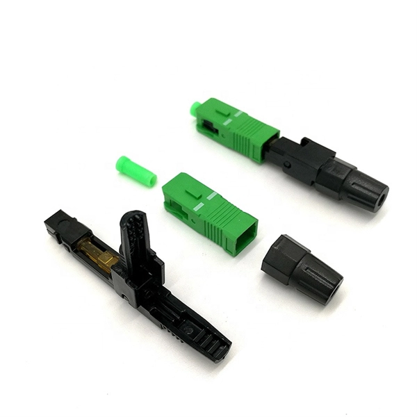
Product Features: Square protective box, suitable for skin cable and leather cable tight protection 6cm in length of skin heat shrink tube welding protection. A close connection between the leather cable and pigtail. Looking for specific info?. *In the era of high bandwidth, reliable fiber optic power equipment is particularly important. This handheld photometer can help check cable performance, calculate relative power loss, locate faults, and troubleshoot. *Measure the length of network cables, coaxial cables, and telephone cables. Able. Usually ships within 3 to 4 weeks Click here for details of availability. Able to test open, short, cross-connect, See more product details TABKER 4000667180167 3 x 2 x 1. Check each product page for other buying options. Price and other details may vary based on product size and color. Need help?. power across any given fiber. This document will serve as an overview of the major features and functions of the device and will ofer tips for trouble shooting com on issues in optical networks. If you are looking for a low cost device capable of saving and reporting take a look at the RP460 or. ments to the instrument's performance and functionality. The figures given in this manual ion of this manual to ensure the accuracy of its contents. However, should you have any questions or fi gistered users with a variety of information and services. Please allow us to serve you best by.
[PDF]

A fiber-optic splitter, also known as a beam splitter, is based on a quartz substrate of an integrated waveguide optical power distribution device, similar to a coaxial cable transmission system. The optical network system uses an optical signal coupled to the branch distribution. The fiber optic. In the backbone of modern Fiber-to-the-Home (FTTH) networks, optical splitters serve as the unsung heroes that enable cost-efficient connectivity for millions of subscribers. By dividing a single optical signal from a central Optical Line Terminal (OLT) into multiple outputs for Optical Network. Optical splitter, also called optical beam splitter, is an integrated waveguide optical power distribution device that can split an input optical signal into two or more output optical signals, and the optical input power is evenly distributed on all output ports. For example, an optical splitter. The answer lies in a small device. We call it an Optical Splitter. This device is the heart of Passive Optical Networks (PON). It allows service providers to save money. It helps them distribute bandwidth efficiently. In this article, we explain the definition, working principles, types, and. An optical splitter is a device that divides light transmission in a network into multiple output ends. It plays a crucial role in facilitating network interconnections.
[PDF]
At Multilink, we offer traffic power solutions to keep traffic signals, camera equipment, illuminated street signs and other tech up and running. Power traffic signals, camera equipment, lighting and other t.
[PDF]

Continuous-wave operation (cw operation): The laser is continuously pumped and emits light continuously, either on a single resonator mode (→ single-frequency operation) or on multiple modes (see also: single-mode operation). How do optical. EML stands for Externally Modulated Laser (corrected from "External Modulated Laser"). Its basic principle is to supply a constant current to the laser diode, ensuring the LD emits continuous, stable light. An external electro-absorption modulator (EAM) then adjusts light transmittance to generate. A wavelength swept light source emits laser light with a continuously sweeping wavelength. It is suitable for shape measurement and displacement measurement utilizing OFDR (Optical Frequency Domain Reflectometry), an optical sensing method using the coherence of laser light. The transmitting interface inputs electrical signals of a certain bit rate, which are then processed by internal driver chips. Subsequently, the driver semiconductor laser. Industry pundits have recently speculated that demand for 100G/400G switches may take off in 2019, prompting optical transceiver module vendors to sample data center switches with high data transmission rates earlier than expected. As data center operators accelerate upgrades in preparation for 5G.
[PDF]

Average Optical Power: How bright the light is (measured in dBm). Too dim? Your signal gets lost in the fiber. Extinction Ratio: The difference between “on” (1) and “off” (0) light power. A higher ratio = cleaner signals. Transmitter Side: An electrical signal hits a laser diode (LD) or LED, which spits out light. Receiver Side: Light enters a photodetector (like a tiny solar cell), which turns it back into electricity. A built-in amplifier boosts the signal for your. The average transmitted optical power refers to the optical power output by the light source at the transmitting end of the optical module under normal working conditions, which can be understood as the intensity of light. In communication, we usually use dBm to represent optical power. However, in practical use, we adopt the average Tx power. The transmission power is related to the. This article provides an in-depth analysis of two key performance indicators of optical modules: transmitter power and receiver sensitivity. Transmitter power characterizes the average optical power output from the laser under rated conditions, while receiver sensitivity indicates the minimum. An optical module is a connecting module that serves as an optical-electrical conversion device. At the receiver end, the optical signals are reconverted into electrical.
[PDF]

Here's a list of the best Routers for Enterprise. Filter the results based on user ratings, pricing, features, platform, region, support, and other criteria to find the best option for you. 1. Full-service routers designed to serve as enterprise WAN core nodes, large enterprise network access nodes, DCI nodes, and campus or large-scale IDC network egress. Optical networking equipment includes fiber optic cables, transceivers, switches, and routers. The market is driven by the. Our Engineers take a hands-on approach to replicating networks, maintaining reliability and providing the highest level of service. Wi-Fi 6 (802. 11ax) indoor wireless access point Dual-radio, dual-band Up to. Desktop All-in-One enterprise-class wireless router Including 5 Gigabit ethernet ports. Reyee 10-Port Gigabit Cloud Managed Router 10-Port Gigabit Cloud Managed. Reyee 10-Port Gigabit Cloud Managed PoE Router 10-Port. Future-proof your network with our full-stack offer. Get started with the right security solution for you. See more, move faster, go farther. Human. To provide secure, reliable affordable and high quality converged telecommunication services anytime, anywhere for an accelerated inclusive socio-economic development. To develop a robust and secure state-of-the-art telecommunication network providing seamless coverage with special focus on rural.
[PDF]

A good laser source for a singlemode link will have a power output of ~ +3 to +6 dBm - 2-4mw - coupled into the fiber. Tx power (transmission power) refers to the intensity of the optical signal output by the transmitting end of the optical module. However, in practical use, we adopt the average Tx power. These modules, including SFP, SFP+, and SFP28, are widely used in enterprise networks, data centers, and carrier-grade deployments. Optical loss is measured in “dB” which is a relative measurement, while absolute optical power is measured in “dBm,” which is dB relative to 1mw optical power Loss is a negative number (like –3. 2 dB) while power measurements can be either positive (greater than the reference) or negative (less than. SFP (Small Form-Factor Pluggable) modules are compact transceivers that allow for high-speed communication between network devices. They are essential in applications like telecommunications, data centers, and enterprise networks. Generally, the power levels are specified in terms of transmit (TX) power and. Transmit power is the power at which the transmitter of an optical transceiver module transmits optical signals in dBm. When the signal received is outside of the range, there is a.
[PDF]
If you encounter any of these issues, check the optical connector for damage or dirt, inspect the fiber optic patch cord, ensure the optical module is correctly installed, and check the device settings for compatibility. Subsequently, the driver semiconductor laser (LD) or light-emitting diode (LED) emits modulated optical signals at the corresponding rate. After transmission through the optical fiber, the receiving interface converts the optical signals into electrical signals using a photodetector diode and. An optical module is a typically hot-pluggable optical transceiver used in high-bandwidth data communications applications. Optical modules typically have an electrical interface on the side that connects to the inside of the system and an optical interface on the side that connects to the outside. The Transmitter Optical Sub Assembly (TOSA) is responsible for the emission of light. Its primary function entails converting electrical signals into optical signals.
[PDF]

It emits a stable red light driven by a constant current source, which is coupled into the optical fiber through an interface to perform fiber fault detection functions. These include checking fiber connectivity and locating faults such as fiber breaks and bends. The B5 Rechargeable Red Light Pen is a professional 650nm visual fault locator designed for fiber optic network maintenance, installation, and troubleshooting. Its advanced rotary automatic lift laser head ensures smooth operation, while the integrated LED lighting improves visibility in low-light. Luxbond LBTEK Fiber Optic Red Light Pen (also known as a pen-style visual fault locator or fiber optic fault detector) uses a 650 nm semiconductor laser as the light source. Note: Meant for use with polished, terminated fiber cables. Always insert and remove the fiber connector without bending the connector to avoid breaking. The RPEN-210 is a necessity tool that should not be missing from any fiber plant manager or fiber optic installing technician. The Visual Fault Locator (VFL) Pen has a visible red light source centered on 650nm. Tool sends visible light over a fiber strand with a 10mW power, good enough to reach. ● Practical Design: Small size and lightweight, pen-type design with pouch make it portable. Design with a stainless steel head and aluminum body to prevent crash and dust, the case ground design prevents ESD damage efficiently Temp. Only registered users can write questions.
[PDF]

To use a power meter for fiber optic testing, always clean connectors first with lint-free wipes or click-to-clean tools. Select the correct wavelength and set your reference. You measure optical power in dBm or insertion loss in dB. Consistent procedures ensure accuracy. Verify light travels from. The most basic fiber optic measurement is optical power from the end of a fiber. This measurement is the basis for loss measurements as well as the power from a source or presented at a receiver. Typically both transmitters and receivers have receptacles for fiber optic connectors, so measuring the. An optical power meter measures the strength of light traveling through a fiber optic cable, giving you a reading in dBm (decibels relative to one milliwatt). This article will guide you through the methods, instruments, and key considerations for measuring fiber. Fiber optic cabling is the high-performance core of today's datacom networks. As network speeds and bandwidth demands increase, fiber performance requirements have become more stringent. Fiber testing is more important than ever. An OPM uses a photodiode to generate an electrical current proportional to optical power.
[PDF]
Fixed fiber optic attenuators are used to reduce the optical power signal in communication links. They work analogous to a step-down transformer. As the signal approaches a device or node in a communication link the power is reduced to a level that is suitable for its application. They are used to control the power level of optical signals at the outputs of light sources and electrical-to-optical (E/O) converters. Measured in decibels (dB), loss degrades signal quality, limits distance, increases bit-error rate, and escalates infrastructure cost. Understanding and managing it is critical to. The Fiber optic attenuator is an optical device that reduces the energy of the optical signal—used to attenuate the input optical power to avoid the distortion of the optical receiver due to the input optical power being too strong. It works by dissipating a portion of the optical power passing through it, thereby lowering the overall power level. Fiber optic attenuators.
[PDF]
Main Source of Lighting for Household by District, Region, and Type of Locality. PxWeb Mark your selections and choose between table on screen and file format. Marking tips Ghana Statistical Services ©2024 | Terms & Conditions. It's helps to drag strangers and robbers from your house when you're away. - 3MP HD Image: The security camera light bulb with 3MP super HD image,let you see the every details. This Lethe battery powered twin security light features a PIR sensor which is a great deterrent for. Dummy security. With over 20 years of experience in the industry, Response has a proven track record of providing high-quality remote monitoring services for our clients. Through the use of advanced technology, we are able to monitor clients' properties 24/7 and receive real-time alerts whenever an alarm is. Buy Remote Home Monitoring Systems Online from Jumia Ghana - Choose from Our Collection of Remote Home Monitoring Systems and Shop them at the best price. Enjoy Cash On Delivery | Secure Payment | Free Returns & more!. 24/7 remote security monitoring and rapid response services. Our experienced team uses the latest techniques and quality materials to. The company offers a comprehensive cloud-based Teleradiology-Platform-As-A-Service (TPaaS) that facilitates secure and efficient management of medical images, making it highly relevant for remote monitoring in healthcare.
[PDF]

The FLS-140 is the easiest way to identify optical fibers from end to end and locate polished connector endfaces. Its red laser shines through most yellow-jacketed optical fibers to help you pinpoint breaks, bends, faulty connectors, splices and other causes of signal loss. A Visible Fault Identifier (VFI), also referred to as a Visual Fault Locator (VFL), is an essential tool for fiber installation and maintenance technicians. AFL's compact VFI4 injects high-powered red-laser light to provide exceptional brightness and range for locating defects in single-mode and. The B5 Rechargeable Red Light Pen is a professional 650nm visual fault locator designed for fiber optic network maintenance, installation, and troubleshooting. Its advanced rotary automatic lift laser head ensures smooth operation, while the integrated LED lighting improves visibility in low-light. Whether installing or troubleshooting, the Visual Fault Locator (VFL) is an essential tool that quickly and easily locates problem areas in fiber cables. By pinpointing the exact location of fiber damage, technicians can diagnose, troubleshoot, and fix the problem efficiently. The VFL is also used. The state, throughput, and identification of an optical fiber can be easily checked with fiber testers by coupling highly visible laser light into the optical fiber. A high intensity visible red laser beam is precision-coupled.
[PDF]


